


Chapter 2: Install the server hardware
22
6.
Press the rail lock button (callout A) and slide the enclosure into the rack (callout E).
7.
Ensure the enclosure retention lock (callout F) closes completely.
Next steps
You can now connect the power cables to the OmniCube servers.
Connect the network cables
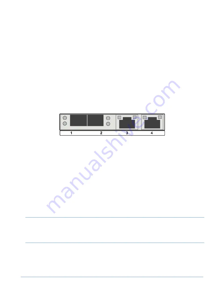
An OmniCube host includes four network interfaces, located on the back panel of the system
enclosure, which are required for the Federation networks. These interfaces are labeled 1 to 4, from left
to right. Network interfaces 1 and 2 are 10GbE and network interfaces 3 and 4 are 1GbE.
Procedure overview
Read the following information before performing the procedure.
For information about the ports required by SimpliVity servers, see the
SimpliVity OmniStack Host
Deployment Guide
.
Figure 9: OmniCube host network ports
The other networking interfaces are:
■ A separate 1GbE IPMI network interface that you can use for the initial system setup and remote
out-of-band management.
■ An optional 1GbE or 10GbE network interface for guest VM use.
Procedure
1.
Obtain the network cables needed for the network configuration.
2.
Connect the cables according to the guidelines for the SimpliVity networks only.
3.
Ensure that no other network interfaces, such as optional 10GbE interfaces, are connected to
your network before deploying the system to a Federation. You can connect these interfaces after
deployment.
Note:
If the optional interfaces are connected when you deploy the system, the ports for the Federation
network might not be configured correctly. For help with resolving this error, contact
Customer
Support
.
Next steps
You can now, optionally, use the Cable Management Arm (CMA) to organize the cables.