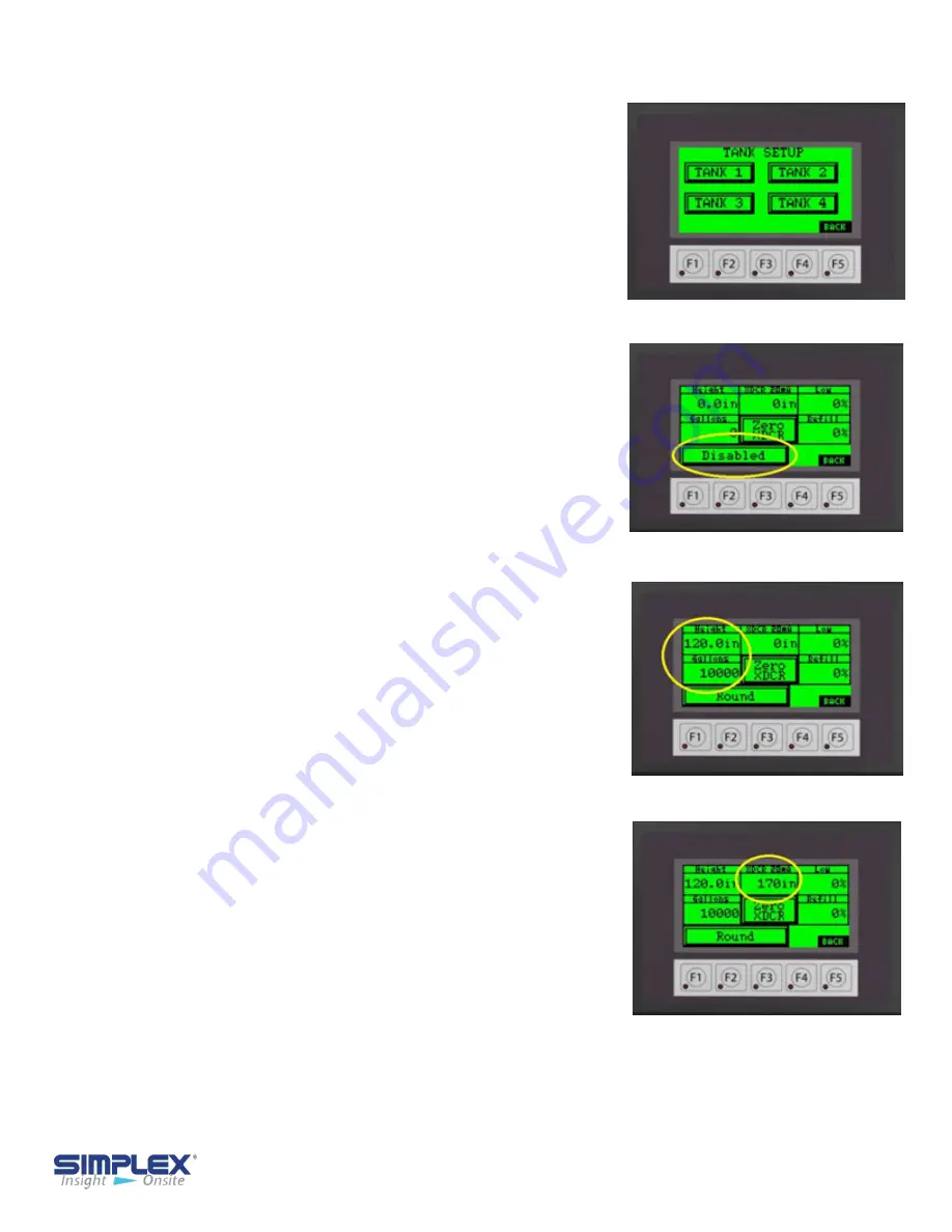
Tank Setup
-
12
Tank Setup
Tank Type Setup
Tank Transducer 1
Tank Transducer 2
Tank Setup
The controller must be configured for your tanks.
Select tank 1-4 buttons to access each tank setup
screen by pressing the respective tank soft key
button on the touch screen
. (See
Tank Setup
)
To activate the selected tank, press th
e
"
DISABLED
" button to select "
DISABLED
",
"
ROUND
" or
"
RECTANGULAR
" depending on the
type of tank.
(See
Tank Type Setup)
You will now need to enter the tank data used
to calibrate the level transducer. All data will be
entered via a pop up numeric entry key pad
accessed by pressing the data entry field. (See
Tank Transducer
)
Next, enter the tank interior depth/height in
inches in the "
Height
" field.
Enter the
maximum
tank capacity in gallons in the
"
Gallons
" field. (See
Tank Transducer)
You must also enter the transducer length at 20mA
in inches. For system using a
0-5 PSI
pressure
transducer, the length will be
170 In
. For systems
using continuous level transducers, you will enter
the "
Measuring Rang
e" dimension found on the
"
Continuous Level Sensor
" drawing of the
provided drawing packet. (See
Tank Transducer
2)
Once the tank shape, height and volume have
been set, the level transducer for the tank
must be calibrated (zeroed. To do so, remove
the probe from the tank or hold it above the fluid
level and press and release the "
Zero XDCR
"
button several times to verify the measurement is
accurate. When finished, install/return the probe
to the tank. (See
Zero Transducer)


