Loosen the focus/azimuth clamping screw and set the focus and azimuth by running the “pink noise” loop
and adjusting the signal pickup assembly in the same manner as a conventional slit lens. Finalize the “A”
chain installation by again checking the L.E.D. adjustment using Dolby Cat. No. 566 “illumination unifor-
mity” test film. Perform a final “Dolby” level set, and complete any other steps specified by the manufacturer
of the sound processor.
DIGITAL ALIGNMENT
Preliminary Adjustment
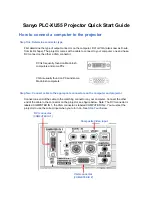
• Power up the second LS-40 Power Supply and the Audio Processor.
• Check for 550 mA output to the digital (outer) L.E.D.
• Connect a dual-trace oscilloscope to the left and right test points of the
processor pre-amp.
• Thread and run Dolby
Tone Test
film (Cat. No. 96t).
• Observe oscilloscope traces and “Dolby” level indicators in the processor.
• If tone is visible on both channels, set to “Dolby” level.
• If not, check the L.E.D. alignment and focus the optics. Then set
“Dolby” level.
• Thread and run SMPTE “Buzz” track.
• Adjust horizontal positioning locknut as required to obtain (2) very low,
equal residual signals.
Analog L.E.D. Alignment
The analog L.E.D.
must
be aligned before the digital.
• Turn both left and right channel pre-amp gain adjustments on your cinema
processor to
full down;
if using a Dolby CP-500, turn to 50%. The goal is to
have equal gain on both channels.
• Thread and run Dolby Tone Test film (Cat. No. 96t).
• View the pre-amp outputs on the oscilloscope screen.
• Rotate the analog L.E.D. mount assembly to reach the maximum ampli-
tude of both traces.
• Move the assembly laterally to get both traces as high and equal as possible.
• Complete the standard “A” chain alignment.
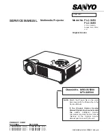
L.E.D. Head
Clamping Screw
Focus/Azimuth
Clamping Screw
Impedance Drum
Azimuth Adjust
Focus Adjust
Horizontal
Positioning
Locknut
Analog Soundtrack
Digital Soundtrack
Analog Signal
Pickup Assembly
10
Содержание APOGEE
Страница 17: ...12 Figure B is in optimal alignment ...
Страница 35: ...30 FILM TRAP Assembly No 52 00223 ...
Страница 39: ...34 APOGEE LENS TURRET Assembly No 52 00279 ...
Страница 45: ...CONTROL CABINET Wiring Diagram 40 ...
Страница 54: ...OIL PUMP ASSEMBLY 49 ...
Страница 63: ......