background image

36

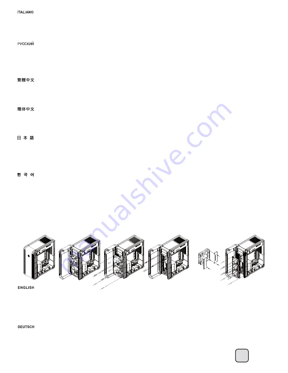
A. Nehmen Sie rechte und linke Seitenwand ab.
B. Öffnen Sie die Frontklappe, entfernen Sie den Lüfterfilter.
C. Lösen Sie die Fixierschrauben des Lüfters, nehmen Sie den Lüfter heraus.
D. Lösen Sie die Schrauben des Lüftergeschwindigkeitsschalters; führen Sie den Schalter durch das Loch an der Frontblende. 
(Hinweis: Bitte verwenden Sie dazu einen kleinen Schraubendreher)
E. Zum Wiedereinbau des Lüfters führen Sie die obigen Schritte einfach in umgekehrter Reihenfolge aus.
Downgrading to a 120mm fan 
1. Fixieren Sie den Lüfter mit normalen Lüfterschrauben an der Halterung, die Sie im FT04-Zubehörkarton finden.
2. Fixieren Sie die Halterung mit der kurzen Schraube (6-32) am Gehäuse.

CP05 e CP05-SAS possono essere acquistati separatamente se si vuole avere la funzione hot-swap. Prendere nota di quanto segue:
A. Se avete bisogno di effettuare un hot-swap mentre è attivo il sistema operativo, dovete essere sicuri che il chipset di controllo del SATA (od il southbridge della scheda madre) 
siano dotati del supporto e dei driver specifici. Per maggiori informazioni su come configurare il vostro sistema per hard disk hot-swap, fate riferimento al video presente presso il 
seguente link: http://www.youtube.com/watch?v=NoNiEMPnSEk
B. Dopo aver impostato correttamente sul sistema la funzione hot-swap, si raccomanda di usare cavi d’alimentazione separati per le unità di sistema e le unità di dati. È meglio 
usare la funzione hot-swap su dischi di dati e collegare le unità di sistema direttamente al connettore SATA 15 pin. (Ignorare queste istruzioni se si usa CP05-SAS)

핫스왑 기능을 사용하려면 CP05와 CP05-SAS를 별도로 구입할 수 있습니다. 다음에 주의하십시오:
A. 운영체제가 동작하는 중에 하드 드라이브를 스왑(핫스왑)핑 하려면, 메인보드 사우스브리지의 SATA 칩셋을 확인해, 드라이버가 하드 드라이브를 정상적으로 
지원하는지 확인해야 합니다. 핫스와 하드 드라이브 장착에 필요한 보다 더 자세한 정보를 는 다음 링크를 참조하시기 바랍니다. 
http://www.youtube.com/watch?v=NoNiEMPnSEk
B. 시스템이 핫스왑 기능을 성공적으로 설치한 경우 시스템 드라이브와 데이터 드라이브용 케이블을 별도로 사용할 것을 권장합니다. 핫스왑 기능은 데이터 
드라이브에서 사용하고 시스템 드라이브는 SATA 15 핀 커넥터에 직접 연결하는 것이 가장 좋은 방법입니다. 
(CP05-SAS를 사용한 경우 위의 지침을 무시하십시오)

あなたが熱い交換機能がありたいならば、CP05とCP05-SASは別に購入されることができます。以下に注意してください:
A. オペレーティングシステム稼働中にハードディスクドライブを交換する(ホットスワップ)必要がある場合、ハードディスクドライブ接続に使用されるSATAチップセット
(またはマザーボードのサウスブリッジ)およびドライバが正しく対応していることを確認してください。ご使用のシステムをハードディスクドライブのホットスワップ対応に設
定する方法については、下記リンクのビデオをご参照ください。http://www.youtube.com/watch?v=NoNiEMPnSEk
B. 一旦あなたがあなたのシステムで熱い交換機能をうまく準備するならば、我々はシステムドライブのために別々のパワーケーブルを使うことを勧めます、そして、データは
運転します。データ・ドライブに関して熱い交換機能を使用して、直接システムドライブをサタ15に接続することがコネクタにピンでとめることは、最高です。(
あなたがCP05-SASを使っているならば、これを無視してください)

如果您有需要SATA hot-swap功能,可以額外選購 CP05或CP05 SAS模組。您可以額外添購2組。但請您注意以下幾點: 
A.如果有需要在開機的狀態下,插拔硬碟(即熱插拔)。請先確認您的SATA控制晶片有支援熱插拔,並已正確的驅動。關於SATA熱插拔的啟動請參考以下影片:  
http://www.youtube.com/watch?v=NoNiEMPnSEk 
B.如果您已經成功使用熱插拔,我們建議您將系統硬碟與資料硬碟的硬碟接線分開。最好是資料硬碟才使用熱插拔模組,而系統硬碟直接使用 Power的SATA 15 Pin接線。
(如果您使用的是CP05-SAS模組,可直接忽略本點)

如果您有需要SATA hot-swap功能,可以额外选购 CP05或CP05 SAS模块。您可以额外添购2组。但请您注意以下几点: 
A.如果有需要在开机的状态下,插拔硬盘(即热插拔)。请先确认您的SATA控制芯片有支持热插拔,并已正确的驱动。关于SATA热插拔的启动请参考以下影片:  
http://www.youtube.com/watch?v=NoNiEMPnSEk 
B.如果您已经成功使用热插拔,我们建议您将系统硬盘与数据硬盘的硬盘接线分开。最好是数据硬盘才使用热插拔模块,而系统硬盘直接使用 Power的SATA 15 Pin接线。
(如果您使用的是CP05-SAS模块,可直接忽略本点)

Если


вы


хотите


пользоваться


функцией


горячего


подключения

можно


приобрести


отдельно


корпуса

 CP05 

и

 CP05-SAS. 

Обратите


внимание


на


следующее

:

A. 

Если


вам


надо


подключить


жесткие


диски


при


запущенной


операционной


системе

 (

горячее


подключение

), 

убедитесь

что


чипсет

 SATA (

или


южный


мост


материнской


платы

), 

используемый


для


подключения


жестких


дисков

поддерживает


эту


возможность

и


нужный


драйвер


установлен

Дополнительную


информацию


о


том

как


настроить


систему


для


горячего


подключения


жестких


дисков

вы


найдете


в


видеоролике


по


ссылке

: http://www.youtube.com/watch?v=NoNiEMPnSEk

B. 

После


настройки


функции

 «

горячего

» 

подключения


компонентов


системы


рекомендуется


использовать


отдельные


кабели


питания


для


системного


диска


и


дисков


данных

Лучше


всего


использовать


функцию


горячего


подключения


с


дисками


данных

а


системный


диск


подключить


непосредственно


к

 15-

контактному


разъему

 SATA. 

(

Это


не


относится


к


корпусу

 CP05-SAS)

A. Remove both right and left side panels.
B. Open the front door and remove the fan filter.
C. Loosen screws holding the fan to remove it.
D. Loosen screws holding the fan speed switch, then route the switch through the hole on front panel. (Note: please use a small screwdriver for this)
E. To reinstall the fan, simply follow the steps in reverse
Downgrading to a 120mm fan: 
A. Secure the fan using normal fan screws onto the transfer bracket that is included in FT04’s accessories box.
B. Use the short screw (#6-32) to screw the bracket onto the chassis.

Upgrade And Maintenance 

A

B

C

D

A

B

(4)  Front fan removal guide

Содержание FORTRESS FT04

Страница 1: ...MANUAL FORTRESS SERIES FT04...

Страница 2: ...grading or performing maintenance on your system A copy of this manual can also be downloaded from our website at http www silverstonetek com Specification P 2 Disassemble chart P 3 Installation guide...

Страница 3: ...tandard PS2 ATX no length limitation Compatible up to 13 3 long width restriction 6 69 8 219mm W x 546mm H x 482mm D 57 6 liters Model No Expansion Card 3 5 x 7 2 hot swap 2 5 x 4 2 x AP182 180mm inta...

Страница 4: ...5 HDD Secure optical drives Secure VGA holder and claw Secure PSU 12025 fan motherboard and 3 5 HDD Motherboard standoff Secure 12025 fan VGA supporter holder VGA supporter claw Standoff screw Cable...

Страница 5: ...4...

Страница 6: ...los de los paneles izquierdo y derecho para quitarlos Per rimuovere i pannelli laterali allentare per entrambi le due viti di serraggio 2 Remove top panel by pushing it toward the rear Entfernen Sie d...

Страница 7: ...facing up 120 Setzen Sie das Netzteil von oben ein sofern das Netzteil ber einen 120 mm L fter oder gr er verf gt empfehlen wir das Netzteil mit dem L fter nach oben einzubauen Ins rez l alimentation...

Страница 8: ...3 5 Loosen the screws holding the lower drive cage to remove it L sen Sie die Schrauben welche den unteren Festplattenk fig fixieren nehmen Sie den K fig ab D vissez les vis pour l enlever en tenant...

Страница 9: ...ssicurarlo alla struttura con le viti in dotazione 2 5 2 5 2 5 2 5 Reinstall the lower drive cage If you want to utilize CP05 you can install it now CP05 Bringen Sie den unteren Festplattenk fig wiede...

Страница 10: ...rd anzuschlie en dies erleichtert die weitere Installation Installez la carte m re sur son support Si vous avez d j install un dissipateur de processeur de grande taille sur la carte m re nous vous re...

Страница 11: ...tier Si vous avez soit le c ble ATX12V 4pin soit le c ble EPS 8pin d j branch veuillez bien v rifier de l avoir pass par l ouverture entre l alimentation et le compartiment de la carte m re Reinstale...

Страница 12: ...necteurs des ports E S de fa ade et tout autre connecteur des appareils du panneau frontal Le recomendamos que empiece a gestionar el enrutado de cables ahora y conecte cables como el ATX 24 pines los...

Страница 13: ...te de alimentaci n por la abertura a la izquierda de la fuente de alimentaci n Convogliare tutti i cavi dell alimentatore verso l apertura alla sinistra dell alimentatore stesso Install 3 5 hard drive...

Страница 14: ...l supporto nel case con i cavi opportunamente sistemati 3 5 3 5 Remove the 5 25 drive bay covers to install required 5 25 devices 5 25 5 25 Dem Sie die Abdeckung der 5 25 Zoll Laufwerksch chte ab inst...

Страница 15: ...rs to install required expansion cards Unused slots should have covers installed Entfernen Sie Steckplatzabdeckungen installieren Sie die gew nschten Erweiterungskarten Bei nicht verwendeten Steckpl t...

Страница 16: ...3 5 dans la cage du lecteur inf rieur Inserte el disco duro de 3 5 en la carcasa inferior para discos duros Inserire il disco rigido 3 5 nel cage unit inferiore 3 5 3 5 3 5 3 5 Reinstall the top panel...

Страница 17: ...luss der Installation die linke und rechte Seitenwand wieder R installez les deux panneaux lat raux pour terminer le montage Reinstale los paneles laterals izquierdo y derecho para completar la instal...

Страница 18: ...necteurs du panneau syst me Les interrupteurs d allumage et de r initialisation ne poss de pas de polarit donc ils peuvent tre branch dans les deux sens Gu a de instalaci n de los interruptores de enc...

Страница 19: ...t des broches des connecteurs du panneau syst me Les c bles color s en blanc noir sont n gatifs alors que ceux d une autre couleur sont positifs Les c bles de la LED Power sont s par s afin d tre comp...

Страница 20: ...veuillez aussi v rifier sur le manuel de votre carte m re de mani re crois e que les broches sont correctement plac es A continuaci n se detallan los pines para conectores E S frontales compruebe tam...

Страница 21: ...e m re L espace vers l avant du bo tier varie selon la fa on dont vous avez remplie le casier disques durs Il y a un espace de 223mm entre le bord des disques durs install s et de la carte m re moins...

Страница 22: ...stin au trou du compartiment de l alimentation utilis pour faire passer les c bles B Recommandations de longueurs des c ble de l alimentation B 1 Below is the recommended cable length for retail ATX m...

Страница 23: ...500 285mm A 225mm 225mm B ATX B 1 Below is the recommended cable length for retail ATX motherboards If the cables are not long enough please purchase extension cables B 2 140mm CPU 8 4 Pin PP04 PP07 A...

Страница 24: ...radiador antes de la instalaci n Ci sono 61mm di distanza tra la scheda madre e l hard drive Se utilizzate memorie simili a quelle mostrate in foto rimuovete il dissipatore superiore prima dell insta...

Страница 25: ...eraci n de servidores SSI CEB placas base para estaciones de trabajo ya no precisan de agujeros de montaje en la bandeja de la placa base para el disipador de la CPU Ahora puede instalar los disipador...

Страница 26: ...cht zwischen zwei benachbarte Grafikkarte passt A CPU Cooler Supporter 1 Premi rement mettez le bo tier sur le c t v rifiez bien qu il soit bien plat 2 Le support int gr du processeur a d j t install...

Страница 27: ...a torre con ventola da 120mm dovrebbero essere perfettamente compatibili B Graphic card supporter 1 Per prima cosa disporre il cabinet su un fianco possibilmente su una superficie piana 2 Installare...

Страница 28: ...slot this will ensure smooth and efficient airflow within the FT04 for maximum cooling performance Bei der Auswahl von Grafikkarten empfehlen wir Modelle die warme Luft ber eine ffnung im hinteren Te...

Страница 29: ...votre c blage Por favor consulte los diagramas siguientes A Existen muchas bridas para cables tras la bandeja de la placa base que puede utilizar para organizar los cables Fare riferimento alle figur...

Страница 30: ...et le panneau lat ral gauche L espace entre le bord sup rieur du casier 5 25 et le panneau sup rieur est galement inf rieur 10mm Ces espaces ont t con us pour renforcer la structure du bo tier et ne s...

Страница 31: ...ine hohe Geschwindigkeit an La vitesse des ventilateurs FT04 Air Penetrator est r glable entre 600rpm 900rpm ou 1200rpm Les vitesses ont t con ues pour une utilisation silencieuse et performante Guide...

Страница 32: ...ach Umgebungsbedingungen Nachstehend finden Sie die Schritte zur Entfernung der L fterfilter La conception pression d air positive du FT04 est une configuration efficace permettant de r duire l accumu...

Страница 33: ...com wheretobuy_all php Beim FT04 werden feinere Luftfilter eingesetzt die einen h heren Luftdurchsatz erm glichen Diese weisen ein identisches Filterverm gen auf jedoch mit einem im Vergleich zu lter...

Страница 34: ...mejor m todo Para evitar que el aspirador da e las aspas del ventilador por favor f jelas antes de limpiar 3 Limpieza con agua Limpiar con agua es el mejor modo de limpiar el filtro del ventilador Tra...

Страница 35: ...etobuy_all php FT04 65 90 1 2 3 http www silverstonetek com wheretobuy_all php FT04 65 90 1 2 3 SilverStone http www silverstonetek com tw wheretobuy_all php area tw T04 65 90 1 2 3 SilverStone http w...

Страница 36: ...erichtet haben empfehlen wir Ihnen den Einsatz separater Netzkabel f r das Systemlaufwerk und die Datenlaufwerke Idealerweise sollten Sie die Hot Swapping Funktionalit t bei Festplatten einrichten und...

Страница 37: ...PnSEk B Dopo aver impostato correttamente sul sistema la funzione hot swap si raccomanda di usare cavi d alimentazione separati per le unit di sistema e le unit di dati meglio usare la funzione hot sw...

Страница 38: ...que sujetan el ventilador para quitarlo D Afloje los tornillos que sujetan el interruptor de velocidad del ventilador luego enrute el interruptor a trav s del agujero del panel frontal Nota por favor...

Страница 39: ...u den Kensington Sicherheitsschlitzen des FT04 passen Kensington Security Slot Un c ble de verrouillage peut tre achet pour utilis l emplacement de s curit Kensington situ l arri re du FT04 pour emp c...

Страница 40: ......

Страница 41: ......

Страница 42: ...41...

Страница 43: ......

Страница 44: ......

Страница 45: ......

Страница 46: ...warranty period please contact your retailer reseller SilverStone authorized distributors or SilverStone http www silverstonetek com Please note that i You must provide proof of original purchase of...

Страница 47: ......

Страница 48: ...Issue date January 2013 G11218050...

Отзывы: