


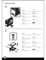


7
5
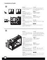
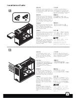
6
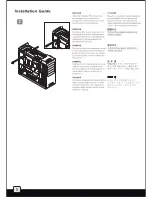
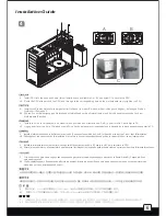
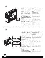
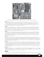
Take the included PSU holder from
the accessory box and secure it
with screw C to the case
Выньте
из
коробки
с
аксессуарами
прилагаемый
держатель
блока
питания
и
привинтите
его
к
корпусу
с
помощью
шурупа
С
.
С
помощью
отвертки
вытолкните
заглушки
переднего
5,25-
дюймового
отсека
для
дисковода
через
овальные
отверстия
,
расположенные
на
передней
части
слева
,
как
показано
на
рисунке
.
Nehmen Sie die mitgelieferte
Netzteilhalterung aus dem
Zubehörkarton, sichern Sie diese
mit Schraube C am Gehäuse.
Prenez le support d'alimentation
inclus dans la boîte d'accessoires
et fixez-le avec des vis de type C au
boîtier
Tome el soporte para FA incluido
de la caja de accesorios y fíjelo con
el tornillo C a la carcasa
Prelevare il supporto per l’alimentatore
dalla scatola degli accessori e
fissarlo con le viti C al case.
Use a screw driver to push out the
front 5.25” drive bay covers through
oval holes located on the left front
side as shown
스크류 드라이버를 이용해, 그림에서와
같이 왼쪽 정면의 타원 구멍으로 밀어
전면 5.25” 드라이브 베이 커버를
제거합니다.
PSU 홀더를 악세사리박스에서 꺼내,
Screw C 로 케이스에 고정시킵니다.
図のように、正面左に位置する楕円形
の穴を通して、フロントの5.25
インチドライブベイカバーをドライバーで
取り出します。
付属のPSUホルダーをアクセサリーボック
スから取り出し、ネジCでケースに固定
します。
用手動起子,鬆開CD COVER,
向前頂,取出CD COVER。
從零件盒內取出電源支撐架,
再用SCREW C 鎖固於機身。
用手动起子,松开CD COVER,
向前顶,取出CD COVER。
从零件盒内取出电源支撑架,
再用SCREW C 锁固于机身。
Drücken Sie die Abdeckungen der
vorderen 5,25-Zoll-Laufwerkseinschübe
wie in der Abbildung gezeigt mit
Hilfe eines Schraubendrehers durch
die ovalen Löcher an der linken
vorderen Seite heraus.
Utilisez un tournevis pour sortir les
caches des baies 5.25” à travers les
trous ovales situé sur le côté avant
gauche comme montré
Use un destornillador para sacar las
tapas frontales de las bahías para
dispositivos de 5,25” a través de los
agujeros ovalados situados en el lado
delantero izquierdo como se muestra
Utilizzare un cacciavite per spingere
all’esterno i cover dei bay da 5.25”
attraverso i fori ovali disposti nella parte
frontale sinistra.
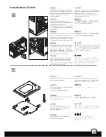
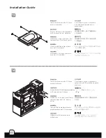
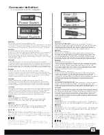
lnstallation Guide
1
4
2
3
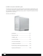
Содержание FORTRESS FT02
Страница 1: ...MANUAL FORTRESS SERIES FT02...
Страница 6: ......
Страница 36: ...September 2009 Issue date G11210830...