


16
AEA111/1
Datum 25.01.2008
Art.Nr. 84155
Änd. Stand 245/07
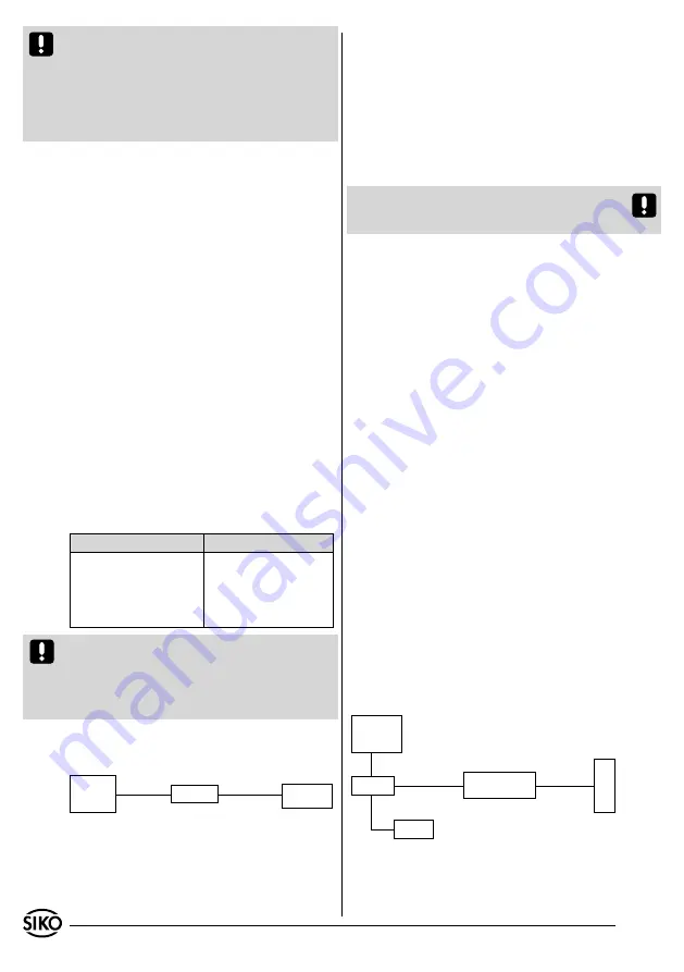
power pack:
24VDC/
500mA
+24VDC/GND
AEA111/1
"SSI-Mode"
cycle+/cycle-/
data+/ data-
eg. MA10/4
SSI
Fig. 2: SSI block diagramm
Configuration of the SIKO magnetic display MA10/4
SSI: encoder type "linear", encoder bits "24", factor
"1.0" (1/100mm display), output code "Gray"
power pack:
24VDC/
500mA
+24V/GND
RS232
RXD/TXD/GND
PC
AEA111/1
"RS485 mode"
DÜA/DÜB/GND
level converter
RS485<->RS232
MSA111
Fig. 3: Block diagram RS485
Attention!
When detecting dynamic operation
or position jump the SSI interface is deliberately
not switched off since this would possibly cau-
se a control unit to detect cable break and enter
the error state. However, the control unit can re-
cognize and check transitory position jumps by a
marginal check.
9. SSI Interface of the AEA111/1
Output of the position value in the SSI mode
With the SSI cycle signal connected the red "SSI
cycle" LED glows. Due to opto-decoupling it glows
even if +24 supply is still switched off.
The integrated SSI interface of the AEA111/1
enables the synchronous output of the position
value, whose data format includes a 24bit width
(1bit (MSB) sign + 23bit position value), output
right aligned. the output code is Gray or binary
(see chapter 6.2). All subsequent bits (25, 26...)
are output "0" (see document "ssi_hard_signa-
le_asa510.pdf").
The data signals comply with the RS422 standard.
the cycle inputs are opto-decoupled and comp-
ly with RS422 as well. The SSI monoflop time is
typically 20...25µs, resulting in a minimum cycle
rate of 62,5kHz.
The maximum cycle rate 1MHz and is basically li-
mited by the length of the connection cable, also
with regard to data safety. the following standard
values apply:
cable length
Max. cycle rate
2m
1MHz
10m
800kHz
100m
250kHz
200m
125kHz
Attention!
The driver output of the SSI interface
is deactivated on the following condition:
The external configuration input was applied to
24VDC while the supply was switched on (see
chapter 12).
Applications example: Position display
•
10. RS485 interface of the AEA111/1
Output of position value and parameterization
in the RS485 mode
The AEA111/1 can be customised to meet indivi-
dual requirement via the integrated RS485 inter-
face. For this purpose, some specific parameters
can be programmed, which are stored in the non-
volatile-memory and can be changed at will.
Attention!
In the RS485 mode the SW1.3 switch
is
not
interpreted while the operating voltage is
being turned on.
10.1 Protocol description of the Service Standard
protocol
The Service Standard protocol enables parameteri-
zation, output of position values and diagnosis of
the AEA111/1. The data signals comply with the
RS485 standard. Since the Service Standard proto-
col is not bus-compatible, no other devices must
be connected to the RS485 interface.
Before turning on the voltage supply, check the
positions of SW1.1 and SW1.2:
DIP-Schalter 1 = OFF
(RS485 mode)
DIP-Schalter 2 = OFF
(Service Standard protocol)
Connect the serial interface of your PC and the
RS485 interface of the translation module by
means of a level transducer (eg. Spectra company
type I-7520).
After turning on the power supply of the AEA111/1
you may immediately start programming by star-
ting a suitable terninal program (eg. "sikoterm.
exe") and manually entering your commands ac-
cording to the "List of commands - Service mode"
table (see chapter 10.1.1). consider the interface
parameters specified.
Applcation example PC/ Terminal