


14
AEA111/1
Datum 25.01.2008
Art.Nr. 84155
Änd. Stand 245/07
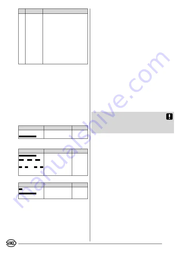
DIP
Position Description
5+6
ON
OFF
Actuation of both switches
within ~2s activates the more
precise position value monito-
ring "millimetre jump" in the
AEA111.
(default) After simultaneous re-
setting of the two switches the
AEA resumes monitoring of the
position values in the "speed
measurement" mode (for the
description see the sensor mo-
nitoring section).
7. Commissioning
After proper installation, wiring and parameteriza-
tion, the translation module can be commissioned
by turning on the 24V supply. With each power-
on procedure, the device goes through a so-called
"startup routine". In this phase, the DIP switches
are read and the translation module is determined
depending on the parameterization (chapter 6).
Constant lighting of the green "Power" LED indica-
tes that the device is ready for operation.
7.1 Status lights of the LEDs
"SSI cycle" LED (red)
Display
Meaning
Action
(OFF) SSI cycle OFF
chapter 9
(ON)
SSI cycle ON
Kapitel 9
"Power" LED (green)
Display
Meaning
Action
(ON)
24VDC ON
--
(ON......OFF.......ON...)
calibration active
chapter 6.2
(2xON.....OFF...2xON...)
Position value monitor-
ing in the millimetre
jump mode
chapter 8.4
"ERROR" LED (red)
Display
Meaning
Action
(ON...OFF) calibration completed
chapter 6.3
(ON)
sensor/ strip gap
cable break
chapter 8
7.2 Sensor alignement
When replacing a translation module, sensor head
or magnetic strip the system must be re-aligned.
The reason is that each sensor is allocated to a
specific translation module following alignment
since the specific sensor data is stored non-volati-
lely in the respective translation module.
The alignment routine can be started via RS485 or
by actuating SW1.4 (see chapter 6.3).
(~2 sec ON, then OFF again)
During alignment, the "POWER" LED blinks evenly.
Smoothly move the sensor head towards the ca-
ble outlet at low speed (~3mm/sec). Alignment
is completed as soon as the "POWER" LED glows
statically again (chapter 6.2).
7.3 Calibration of the measuring system
The AEA111/1 is an absolute measuring system,
i.e. the information of the position value is repre-
sented on the scale as an absolute value.
Following successful sensor alignment, the calib-
ration point can be freely defined at any desired
position.
Calibration can be performed either via RS485 in-
terface or SW1.5 (~1sec. ON, then OFF again).
Afterwards, the value position value = 0 + calibrati-
on value will be output at the current position .
With calibration the current position value is
replaced by the set calibration value and stored
non-volatilely.
Attention!
This value is factory-set to "0"; there-
fore, the position value "0" is displayed as the de-
fault value. the calibration value can be changed
via RS485 (chapter 10.1) and is also stored in the
non-volatile memory.
Calibration relates to one aligned system only
(see chapter 7.2 sensor alignment). The procedure
must be repeated after replacing one of the exis-
ting components!
7.3.1 Calibration in the RS485 mode
In the Service Standard-Protokoll setting (see
chapter 10.1):
Enter the "S00000" interface command (see
chapter. 10.1.1)
or
In the SIKONETZ3 Protocol
(see chapter 10.2):
Entry sequence of interface commands: p r o-
gramming mode ON, calibration, programming
mode AUS (see chapter 10.2)
Telegram example:
To calibrate device with address 1.
Master sends (hex):
81 32 63
AEA111/1 replies (hex):
81 32 63
Short telegram to/ from address 1 (81h);
Programming mode ON (32h); sense byte
(63h)
•
•
1.