Cut a new length of 1/16" music wire about 4" long. Reinstall the
cowl and insert the wire through the cowl and into the hole in the
needle valve and tighten the setscrew. Turn the needle all the way
in and make a mark on the wire, about 1/8" outside the side of the
cowl. Remove the wire from the needle valve and cowl and make
a 90
O
bend in the wire, at the mark. Trim the excess wire from the
bent end, leaving about 3/8" to grip on. Insert the wire back into
the cowl and needle valve and tighten the setscrew. You now have
a neat looking, perfectly aligned needle valve extension.
❑
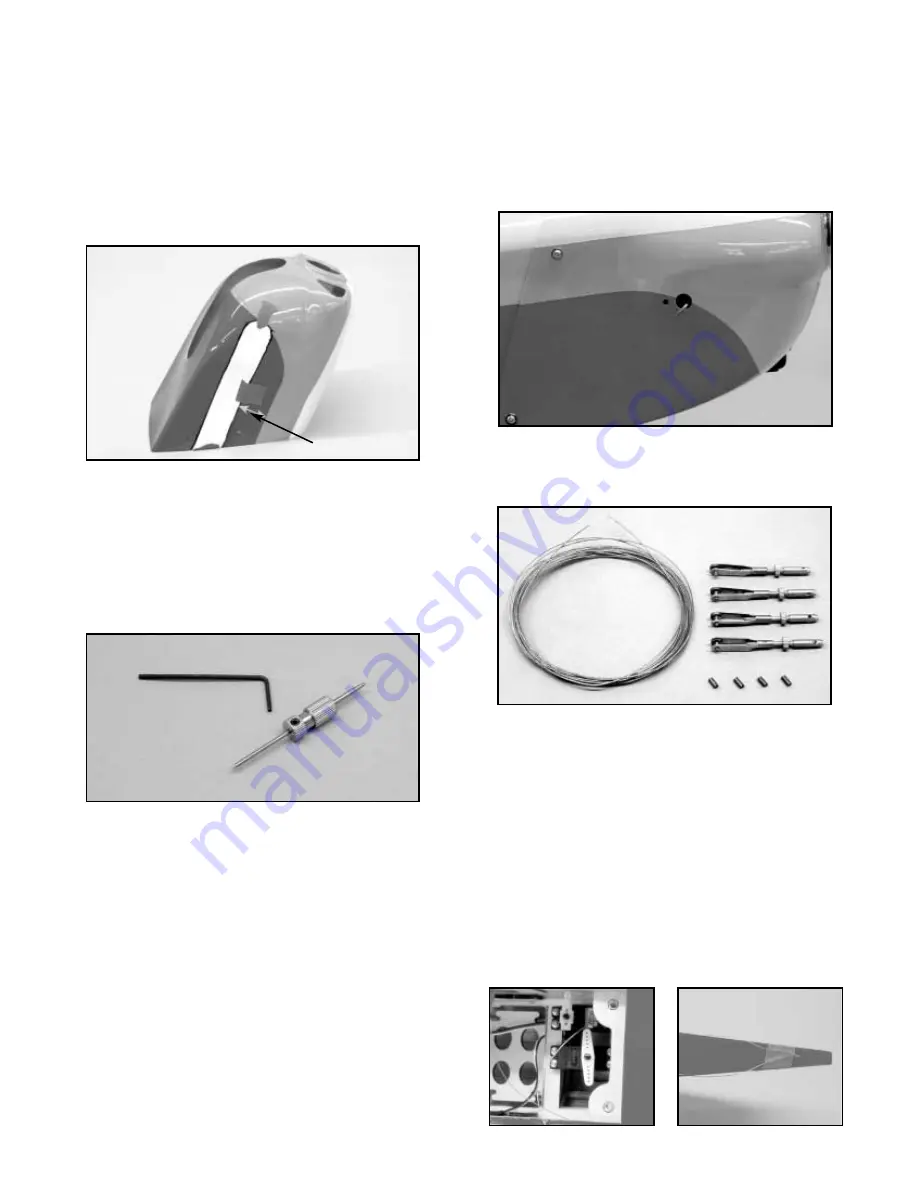
22) The rudder pull-pull system can now be installed. From the
kit contents, locate the 2 Steel Cables, 4 Swage Tubes, 4 Threaded
Rigging Couplers, and 4 Metal R/C links.
Mount the rudder servo in place using the screws and hardware
provided by the servo manufacturer. As previously mentioned, we
highly recommend using the Du-Bro super strength servo output
arms for the pull-pull rudder system.
Plug the servo into the
rudder outlet in the receiver, turn on your radio system and center
the servo, making sure that the transmitter rudder trim is in the
center position also, and install the servo output arm on the servo.
Turn off the radio system.
The pull-pull cables have been
provided in two equal lengths. Insert one of the cables into each
of the pull-pull exits located in the rear of the fuselage. Pass the
cables completely through the rear of the fuselage and up to the
rudder servo location. Keep pulling the cables forward until you
have about eight inches of cable remaining at the rear of the
fuselage. Tape the cables in place at the rear of the fuselage with
small pieces of masking tape to prevent the cable from slipping out
of the pull-pull exit tubes.
❑
20) Most engines will require another cut out in the cowl to clear
the exhaust system. The engine, shown in this manual, is the
YS-63S and the photos show how we cut the cowl to clear its
exhaust system. If you are using a different engine, then you will
have to use the same technique to create the required cowl
clearance hole for your particular engine.
For most engine
installations, there is more than an adequate amount of openings
provided in the cowling for cooling air to enter and exit. A rule of
thumb is that the exit area must be equal to or larger than cooling
air inlet. There should be at least 1/8" of clearance between the
cowling and any accessory such as muffler and/or carburetor.
❑
21) With the cowl now in place, you need to consider the
needle valve. Most engines come with a needle valve that has a
pre-drilled hole in its center and a setscrew. This is used when
attaching a needle valve extension. Our YS 4-stroke has just such
a needle valve assembly and the pre-drilled hole accepts 1/16"
dia. music wire. To locate the required needle valve extension hole
in the cowl, we put a short length of 1/16" dia. music wire into the
hole in the needle valve and tightened the setscrew to hold it
firmly.
The needle is then threaded back in place all the way into the
carburetor. Place a straight edge against the side of the fuselage
at the nose, intersecting the piece of wire and mark this point on
the wire. Remove the wire from the needle valve, cut the wire at
the point you just marked then sharpen the wire to a needlepoint.
Insert the wire back into the needle valve, tighten the setscrew and
install the cowl onto the fuselage. Turn the fuselage upside down
on your work surface and use a pair of needle nose pliers or
hemostats to begin turning the needle out. As the needle rotates
outward, the sharpened end of the wire will come into contact with
the inside surface of the cowl. Hold a scrap piece of wood against
the outside of the cowl, over the pointed wire, and continue
unthreading the needle valve until you get a definite dimple on the
outside of the cowl. When you see this mark, screw the needle
valve back into the carburetor and remove the cowl. Using the
dimple on the cowl for center, use a 3/32" dia. bit to drill through
the side of the cowl. Remove and discard the sharpened piece of
music wire from the needle valve. Make sure the needle valve
setscrew is aligned to allow access to it when the cowl is in place.
10
1-3/16”


