


3
MOUNTING THE ENGINE
We suggest mounting the engine and fuel tank before the wing is
installed in the fuselage, as it is much easier to work on them
without the wing in the way.
❑
1) Assemble the propeller and the 1-3/4" spinner onto your
engine.
❑
2) Cut two 1/16” x 1/4” x 2” shims from balsa or plywood to use
as spacers between the spinner backplate and the front of the
fuselage as shown.
❑
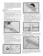
3) Center the engine evenly between the motor mounts and
make sure that the centerline of the engine lines up with the
centerline of the wing cutout. Then mark the locations for the four
engine mounting bolts onto the fuselage.
❑
4) Drill the holes for your engine mounting bolts through the
fuselage at the marked locations. If available, use a drill press to
keep the holes perfectly vertical in the fuselage. After drilling,
place a couple drops of Thin CA in each hole to help seal out fuel
and let dry.
❑
5) Install your blind nuts in the drilled holes on the left side of
the fuselage. Bolt the engine in place and tighten the mounting
bolts to finish aligning the blind nuts. Secure the blind nuts in
place with CA glue.
Note: No right engine offset was required on the prototype. In
fact, the engine was initially offset on the first prototype by placing
washers under the front mounting lugs of the engine and the
washers were later removed during trimming process.
FUEL TANK ASSEMBLY
The fuel tank provided in this kit is a 4 oz. clunk-style plastic tank.
We have used this tank successfully on the Primary Force with
either standard up/down 2-vent plumbing and with “uniflow”
plumbing. The choice for your airplane is up to you, based on your
personal experience and preference. For simplicity, the following
instructions will only show the installation of standard 2-vent
plumbing.
❑
6) The 3 metal tubes (2 curved, 1 straight) supplied with the fuel
tank need to be cut off for the Primary Force 2-vent installation.
a) The two curved metal tubes will be used for the tank vents.
Cut 1/2” off BOTH ends of each curved tube, as shown.
b) The straight tube will be used for the fuel feed line. Cut it to
1-1/2” long.
Cutting Metal Fuel Lines: There are actually several good ways
to go about cutting metal fuel line tubing.
1) Small Tubing Cutter (such as K&S #296).
2) Dremel
®
Tool with Abrasive Cutoff Wheel.
3) Razor Saw (such as X-Acto #239).
Regardless which method you use, be sure that you remove any
burrs from the outside and inside of the cut end. Burrs on the
outside of the tube can cut your fuel line tubing, and burrs on the
inside of the tube can restrict fuel flow. Use fine sandpaper to
clean up burrs on the outside of the tube, and a #11 modeling
knife to remove any burrs on the inside.
❑
7) Assemble the metal tubes in the rudder stopper, as shown.
❑
8) Install the stopper assembly in the tank, along with the
flexible fuel line tubing with the metal klunk weight on the end.