


10
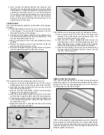
WING TIP WEIGHT
Install 3/4 oz. of weight in the tip weight box (Note: Three of the
SIG 1/4 oz. Lead Weights #SH561 fit perfectly inside the Primary
Force tip weight box). Use small pieces of foam rubber or paper
towels to insulate the lead weights and keep them from rattling in
the box.
ADJUSTABLE LEADOUT GUIDE
The Primary Force is equiped with an adjustable leadout guide
which lets you alter the location of the leadouts at the wing tip.
This is an important flight trim feature that can have a great affect
on achieving proper line tension during aerobatic maneuvers. As
mentioned previously in Step 27, for your initial test flights the
leadout guide adjustment bolt should be located at 2-3/8” aft of the
wing leading edge (or 6-11/16” forward of the trailing edge).
CONTROL SYSTEM
The control system must work free and smooth with an equal
amount of up and down travel.
ENGINE BREAK-IN
Make sure your engine is properly broken in and running properly
before attempting the first test flight.
FLYING THE PRIMARY FORCE
The Primary Force is not a trainer model. It is intended for pilots
who have some previous control-line experience. If you are a new
pilot, please seek the assistance of an experienced control-line
pilot who can help you with your first flights.
ADVANCED FLIGHT TRIMMING
These trimming tips are geared towards experienced stunt fliers
who are seeking the ultimate aerobatic performance from their
Primary Force. Nonetheless, the information provided here can
also be of value to less experienced fliers as their skills progress.
As you become more proficient and begin learning all of the
pattern maneuvers, these tips will help you fine tune your
airplane’s performance to keep up with your improving pilot skills.
HANDLE SPACING
If you are using a control handle that has adjustable line spacing,
set the spacing at 3-1/2” between the lines. During the first few
flights carefully watch the model in the square maneuvers. If the
Primary Force hops when coming out of a square corner then
reduce the line spacing 1/4” at a time until the hop is eliminated.
LINE LENGTH
Start out with 60 ft. lines from the center of the handle to the
center of the model. If the engine is running properly and the lap
times are too fast, increase the line length two feet at a time until
lap times are in the proper range.
LAP TIMES
The Primary Force flies best at 5.0 - 5.3 second lap times. Exact
time will vary slightly depending on which engine you are using
and its running characteristics. EXAMPLE 1: The venerable Fox
.35 Stunt engine likes to fly along at a slower 5.2 lap time and then
speeds up slightly during maneuvers (the classic 4-2-4 break).
Reduce the amount of speed up in the maneuvers with the Fox by
using a 10x5 prop. EXAMPLE 2: The OS LA-25 likes to cook
along in a wet 2-cycle at a 5.0 lap time, but the speed in the
maneuvers ends up being about the same as the Fox 35. As
always, you can adjust to suit your equipment and preferences.
TIP WEIGHT
With 3/4 oz. of weight in the tip weight box the outboard wing
should drop in a hard corner. Make small adjustments, one at a
time. Remove one of the weights from the box and cut off the
corners of the weight. Fly the model and see if the wing drops
again in a hard corner. If it does, cut off the corners of another
weight and fly again.
The Primary Force should pop a turn
without any sign of wobble or hop while exiting a square turn. If
the model feels soft in the overheads, then replace one of the
weights with one that does not have corners cutoff and move the
leadouts forward 1/8".
LEADOUT POSITION
The 2-3/8” starting leadout position (see Step 27) should be really
close to the final trim location. Tip weight has a big effect on the
position of the leadouts, so go easy and move the leadouts slightly
ahead if you add tip weight, and slightly to the rear if you remove tip
weight. Never move the leadouts more than 1/8" at a time.
FLY SAFELY!
Please operate your airplane in a safe, responsible manner with
constant regard to other flyers, spectators, and property.
GOOD LUCK AND HAPPY LANDINGS!
WARNING! THIS IS NOT A TOY!
Flying machines of any form, either model-size or full-size, are not toys! Because
of the speeds that airplanes must achieve in order to fly, they are capable of
causing serious bodily harm and property damage if they crash. IT IS YOUR
RESPONSIBILITY AND YOURS ALONE to assemble this model airplane
correctly according to the plans and instructions, to ground test the finished model
before each flight to make sure it is completely airworthy, and to always fly your
model in a safe location and in a safe manner. The first test flights should only be
made by an experienced flyer, familiar with high performance model aircraft.
JOIN THE AMA
The governing body for model airplanes in the United States is the ACADEMY OF
MODEL AERONAUTICS, commonly called the AMA. The AMA SAFETY CODE
provides guidelines for the safe operation of model airplanes.
While AMA
membership is not necessarily mandatory, it is required by most flying clubs in the
U.S. and provides you with important liability insurance in case your model should
ever cause serious property damage or personal injury to someone else.
ACADEMY OF MODEL AERONAUTICS
5161 East Memorial Drive
Muncie, IN 47302
Telephone: (765) 287-1256
AMA WEB SITE: www.modelaircraft.org
CUSTOMER SERVICE
SIG MANUFACTURING CO. is committed to your success in assembling and
flying the Primary Force ARF. Should you encounter any problem building this kit,
or discover any missing or damaged parts, please contact us by mail or telephone.
SIG MANUFACTURING COMPANY, INC.
401-7 South Front Street
Montezuma, IA 50171-0520
SIG MODELER’S ORDERLINE: 1-800-247-5008
(to order parts)
SIG MODELER’S HOTLINE: 1-641-623-0215
(for technical support)
SIG WEB SITE: www.sigmfg.com
LIMIT OF LIABILITY
The craftsmanship, attention to detail and actions of the builder/flyer of this model
airplane kit will ultimately determine the airworthiness, flight performance and
safety of the finished model. SIG MFG. CO.’s obligation shall be to replace those
parts of the kit proven to be defective or missing. The user shall determine the
suitability of the product for his or her intended use and shall assume all risk and
liability in connection therewith.