


.
KING KOBRA RC54 FUSELAGE CONSTRUCTION
Before beginning the fuselage, give some thought to your engine installation. The following instructions show an angled
installation with the nose gear bearing installed. The angle puts the engine muffler close to the fuselage and places the
needle valve of the engine at an ideal level in relation to the fuel tank. We recommend this location unless you have some
good reason for changing it.
On one of the prototypes the engine was mounted horizontally, which had the advantage of making it easy to run the tuned
pipe under the wing. This horizontal position is only possible if you are using a retract gear and won't have the nose gear
bearing in the way on the front of the firewall. A tuned pipe located on the side of the fuselage may require a nearly vertical
or vertical position to work out properly, depending on what shape headers are available for your engine and pipe. For
engine locations that put the needle valve above the recommended position it might be advisable to fit a fuel pump, such
as the Perry Micro-Oscillating Pump, to minimize fuel level change effects and obtain optimum engine operation. However,
the amount of variation from the ideal level is not very large so this may not be a problem. If a fuel pump is not used, a
muffler or pipe pressure tap to the tank is recommended.
The photo shows a horizontally mounted
engine with a Perry Micro Pump installed
in the King Kobra. Note that the firewall
had to be ground away a bit with a
Dremel tool to clear the pump mounted
on the back of the engine. Since the
firewall is 3 laminations thick, this was
no big deal, there was still plenty of
wood left to do the job. However, other
engines may be bulky enough to require
more room in the rear. We suggest here
an easy method of getting more
clearance behind the engine by
lengthening the cowling.
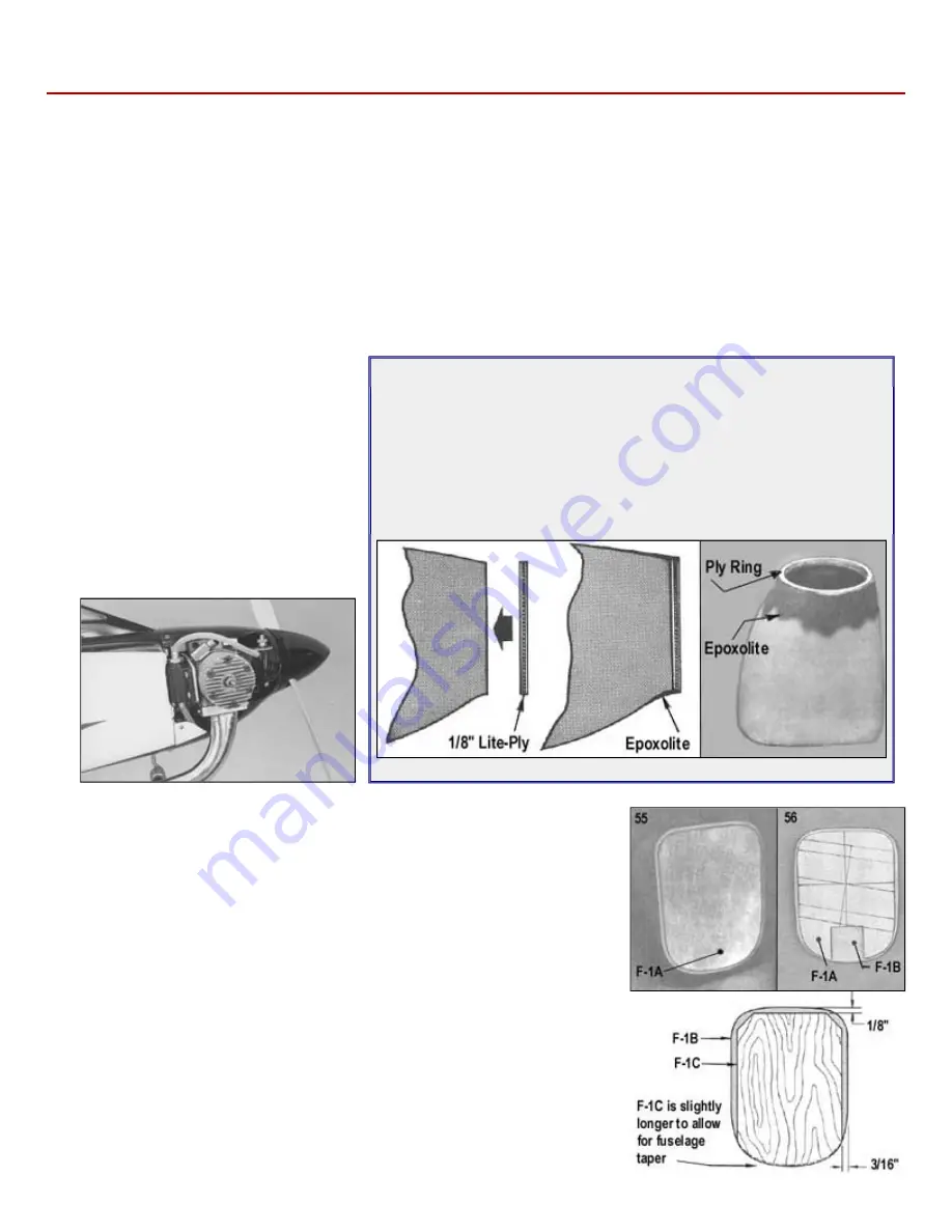
Optional Cowl Extension
The average .60 will not need this addition to the cowl. We show it here for
your information should extra room be required.
Sand the gloss off and roughen the plastic in the areas where the Sig
Epoxolite putty will be applied. (The putty will almost become an integral
part of the plastic if this procedure is followed.) Glue a plywood ring - in this
case it was one of 1/8" Lite Ply - to the front of the cowl. Fill the joint with
Epoxolite and blend it into the lines of the cowl.
55.
Sand any rough edges of F-1A, F-lB and F-lC. Fit F-lA inside the cowling.
56.
Draw layout lines on F-1A ot the proper width for the mounts and engine to be
used and at the angle chosen for mounting. Glue F-1A to the front of F-1B. Use
the cowl to check for correct position. If they should happen to be warped (a
congenital problem with plywood), clamp them together between two flat plates in
a vise while the glue is setting up.
NOTE: Leave the cut-out for the nose gear bearing in F-1A on for retract
versions.
57.
Glue F-1C to the back of F-1B with epoxy.
58.
Here's a handy way to fit the mounts to your engine. It temporarily turns them into
a one piece mount.
a. Layout guide lines on a piece of scrap 1/16" plywood of the proper width
and height.
b. Mark the top of the mounts on the sides so they can be accurately located.
c. Glue them in place on the scrap scab.