19 – 9
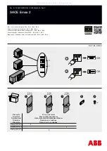
For frame size III, draw out version:
NOTE
Working through step
9
, the intermediate shaft must engage in a hole inside the circuit breaker.
Only then it will be possible - working through step
10
- to fit the support for the intermediate shaft in the guide of the side wall.
mechanical interlocking module
with ringg
2
3
4
5
Hold
6
7
8
9
Содержание UL 1066
Страница 43: ...6 12 7 Reset reclosing lockout 8 Charge closing spring 9 Switch ON Frame size II Frame size III 9X ...
Страница 56: ...7 5 7 2 Frame size II fused ...
Страница 58: ...7 7 ...
Страница 63: ...7 12 8 27 210 0 8 27 210 0 8 27 210 0 3 75 95 2 ...
Страница 64: ...7 13 ...
Страница 65: ...7 14 7 7 Frame size III fuse carriage ...
Страница 66: ...7 15 ...
Страница 69: ...7 18 7 9 External sensor for neutral conductor WLNCT2 ...
Страница 70: ...7 19 WLNCT3 ...
Страница 85: ...9 5 I tripping Ground fault tripping ...
Страница 231: ...15 12 Pre assembling the locking module Installing 0767 1 2 3 4 6 5 ...
Страница 232: ...15 13 1 Socket head cap screw M5 with washer and nut 7 8 Size 4 5 Nm 45 lb in ...
Страница 271: ...19 10 Function check Then Fit back front panel and side cover on the right if it was removed page 23 4 10 ...
Страница 280: ...21 2 Installing the door sealing frame Not for use with fuse carriages Catalog No Door sealing frame WLDSF 1 2 3 NOTICE ...
Страница 289: ...23 7 23 3 3 Installing arc chutes 1 2 6 5 PH 2 0043 02 3 4 5 6 For frame size III 3 PH 2 ...
Страница 298: ...23 16 6 7 8 9 5 2 1 Size 5 mm ...
Страница 333: ......


