Document No. 997-1002
Installation Instructions
February 12, 2009
Information in this publication is based on current specifications. The company reserves the right to make changes in specifications and models as
design improvements are introduced. Other product or company names mentioned herein may be the trademarks of their respective owners.
© 2009 Siemens Building Technologies, Inc.
Siemens Building Technologies, Inc.
1000 Deerfield Parkway
Buffalo Grove, IL 60089-4513
U.S.A.
Document No. 997-1002
Country of Origin: US
Page 8 of 8
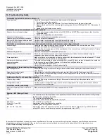
16. Troubleshooting Guide
Controller is powered but does not turn on
Fuse has blown
Check the fuse integrity. If the fuse has blown, perform the following:
1. Turn off power from the controller.
2. Remove the front plate of the controller. The fuse is located close to the power terminals.
3. Replace the fuse with a 2A fast-acting high-breaking capacity fuse (1500A @ 250VAC). Dimensions: 5
x 20mm.
4. Reattach the front plate to the controller.
Controller cannot communicate on an FTT network
Absent or incorrect supply voltage
1. Check power supply voltage between the 85-265VAC and NEUTRAL pins and ensure that it is within
acceptable limits.
2. Check for a tripped fuse or circuit breaker.
Network not wired properly
Double check that the wire connections are correct.
Absent or incorrect network termination
Check the network termination(s).
Incorrect APB file has been downloaded
Use the memory erase jumper to reset the Neuron chip's memory.
Service pin not working
Use the memory erase jumper to reset the Neuron chip's memory.
Controller communicates well over a short network, but does not communicate on large network
Network length
Check that the total wire length does not exceed the specifications of the
Junction Box and Wiring
Guideline for Twisted Pair LonWorks Networks
.
Wire type
Check that the wire type agrees with the specification of the
Junction Box and Wiring Guideline for Twisted
Pair LonWorks Networks
.
Network wiring problem
Double check that the wire connections are correct.
Absent or incorrect network termination
Check the termination(s). Incorrect or broken termination(s) will make the communication integrity
dependent upon a controller’s position on the network.
Extra capacitance
Make sure that no extra capacitance is being connected to the network other than the standard FTT circuit
and a maximum of a 3 meter stub (in bus topology).
Number of controllers on network
segment exceeded
The number of controllers on a channel should never exceed 64. Use a router or a repeater in accordance
to the
Junction Box and Wiring Guideline for Twisted Pair LonWorks Networks.
Network traffic
Query node statistic to check errors.
Use a LON protocol analyzer to check network traffic.
Hardware input is not reading the correct value
Input wiring problem
Check that the wiring is correct according to this document and according to the peripheral device’s
manufacturer.
Open circuit or short circuit
Use a voltmeter, check the voltage on the input terminal. Short circuit (0V) and open circuit (5V).
Configuration problem
Use the controller configuration plug-in to check the configuration of the input. Refer to the controller’s user
guide for more information.
Hardware output is not operating correctly
Output wiring problem
Check that the wiring is correct according to this manual and according to the peripheral device’s
manufacturer.
Configuration problem
Use the controller configuration plug-in to check the configuration of the output. Refer to the controller’s
user guide for more information.
Controller resets periodically
Short circuit between 24VAC OUT and
COM
Make sure that the 24VAC OUT is not connected to the COM.
Service LED (Orange Color)
Off
The controller is in normal operation or not powered (if the controller is powered and the LED is off, pressing
the Service Pin will light up the LED).
On
The controller is application-less.
Appropriate action: Reload the application file (.apb).
Slow Blink
(1 sec. On, 1 sec. Off)
The controller is unconfigured.
Appropriate action: Commission the controller.
Fast Blink
(0.3 sec. On, 1 sec. Off)
Watchdog time out. Application corrupted.
Appropriate action: Use the memory erase jumper to reset the Neuron chip's memory, and then load the
proper APB into the controller using a network management tool (e.g. LMT).

