Document No. 997-1002
Installation Instructions
February 12, 2009
SLX Series
Page 5 of 8
2-Line Main
Power Disconnect
L
N
Fuse
DOx
Cx-x
DOx
Relay
A2
A1
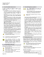
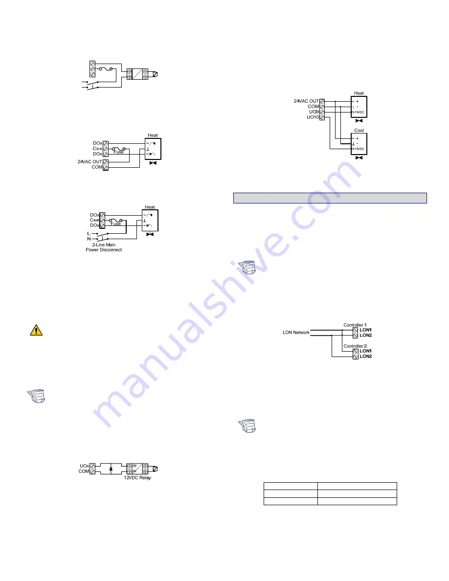
Figure 14: Digital Triac Output with Ext. 85-265VAC
Power Supply – Relay.
Figure 15: Digital Triac Output with Onboard 24VAC
Power Supply – Floating Actuator.
Figure 16: Digital Triac Output with Ext. 85-265VAC
Power Supply – Floating Actuator.
Wiring the Universal Outputs
Onboard 24VAC Output Specifications
Voltage:
24VAC; ± 15%; 50Hz
Maximum Consumption: 300mA (7.2VA) @ 24VAC
Do not connect the 24VAC OUT to UIx or UOx.
Universal outputs can be configured to provide either a
discrete signal of 0 or 12VDC or a linear signal ranging from
0 to 10VDC. The discrete signal can be used to generate a
pulse wave modulation (PWM) signal or a simple two-state
signal.
Analog output cables should be between 22 and
18AWG.
Wiring Discrete Outputs
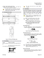
When controlling a relay with a universal output, a diode
must be connected in parallel to protect the controller from
back-emf current, which occurs when the relay is turned off.
It is recommended to use diodes that are part of the 1N400x
family, and they should be placed closer to the relay.
Figure 17: Discrete 0 or 12VDC Universal Output – Relay.
Wiring Voltage Outputs
Connect the 0 to 10VDC output according to the following
figure if an analog actuator is being controlled.
Figure 18: Voltage 0-10VDC Universal Output – Analog
Actuator.
11. Communications Wiring
The recommended cable type for LON
®
communications is
22AWG (0.65 mm), twisted pair, unshielded. The LON
communication wire is polarity insensitive and can be laid out
in a bus, star, loop or free topology. For loop topology, polarity
is important and special care must be taken when connecting
the LON network to avoid a short circuit.
It is recommended to use the bus topology network
configuration for all LON communication wiring, as
it allows for easy network troubleshooting.
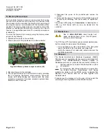
Connect both wires to the LON 1 or 2 terminals of the
controller. If inserting multiple wires in the terminals, ensure
that the wires are properly twisted together prior to inserting
them in the terminal connectors.
Figure 19: Communications Wiring.
For more information and detailed explanations on network
topology and wire length restrictions, refer to the
Junction Box
and Wiring Guideline for Twisted Pair LonWorks® Networks
,
published by Echelon
®
Corporation.
It is important to use proper network terminators
depending on the type of network topology used.
Failure to do so can result in communication errors
between controllers. Do not use multiple gauges of
cable on the same communication bus, as this may
also result in communication errors.
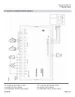
Selecting Network Terminators
Topology Part
#
Bus PDIDI-BT-TP10XX
Free PDIDI-FT-TP10XX
For a bus topology, two network terminators are required
(one at each end of the bus topology channel). For a free
topology, one network terminator is required, and it can be
put anywhere on the channel.

