Document No. 997-1002
Installation Instructions
February 12, 2009
SLX Series
Page 3 of 8
3. Remove the back plate and drill holes.
4. Finally, clean the perforated surface and fasten the
controller using the appropriate screw types.
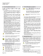
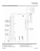
6. Controller Dimensions
Figure 3: PFCU and PTU Dimensions.
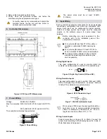
7. Power
Wiring
Voltage:
85-265VAC; 50-60Hz
Max. Consumption: 33VA (SLX-ASC-PFCU-A and SLX-P-PTU-
A)
20VA (SLX-ASC-PFCU and SLX-P-PTU)
The controller is internally fuse-protected.
Figure 4: Power Wiring.
The power wires must be at least 18AWG
(1.024mm).
8. Input
Wiring
Each controller has physical connections for six (6) inputs that
are software configurable from within the controller's LNS
®
plug-in. Each input can be configured for digital, resistive,
current or voltage signals. Input types must be configured
properly in the software plug-in to ensure proper input
readings.
Before connecting any input equipment to the
controller, refer to the installation guide of the
equipment manufacturer.
•
For a wire length less than 75’ (23m), either a
shielded or unshielded 18AWG wire may be
used.
•
For a wire length between 75’ and 200’ (23 to
61m), a shielded 18AWG wire is recommended.
•
The wire should be shielded on the controller
side and the shield length should be kept as
short as possible.
Wiring Digital Inputs
This input configuration is used to monitor digital dry
contacts, as well as pulsed contacts (PTU controllers only).
Figure 5: Digital Dry Contact (NO and NC).
Wiring Resistive Inputs
This input configuration is used to monitor 100
Ω
and 1000
Ω
RTDs, 10k
Ω
type II and III thermistors, as well as 10k
Ω
and
100k
Ω
(PTU controllers only) potentiometers.
Figure 6: RTD /Thermistor Input.
Figure 7: 10k
Ω
Potentiometer Input.
When using a 100
Ω
input, the wire length should be
kept short so as to avoid a possible temperature
offset. For example, an 18AWG wire, 25’ (7.6m) in
length can create an offset of 2°F (1.1°C).
Wiring Current Inputs
Current inputs have a range of 4 to 20mA. Connect the
current input according to the following figure if a 2-wire, 4-
20mA transducer is being used.
For safety reasons it is recommended to install the
controller inside the fan coil unit box. Refer to
national and local electrical codes.

