


SIPART DR19
68
C73000-B7474-C140-06
Configuring
Quick Reference
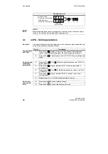
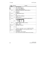
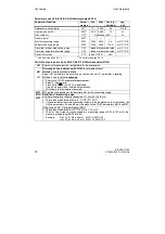
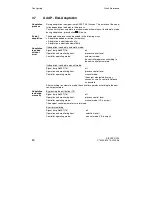
Logic of DO on allocated control signals
24 V = High
0 V = High
S76
S77
S78
S79
S80
S81
S82
RB
[0]
1
RC
[0]
1
H
[0]
1
Nw
[0]
1
A1/A2
[0]
1
A3/A4
[0]
1
MUF
[0]
1
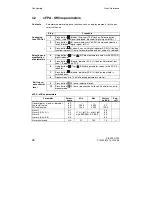
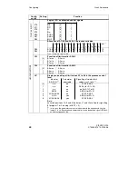
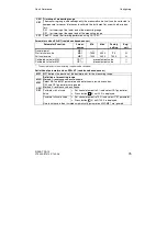
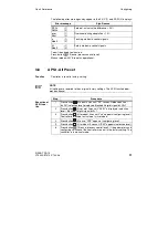
Allocation of A1/A2 and A3/A4 to process variables
xd x1 x
w xv wv y y1 y2 AI AI AI AI AI AI
|xd|
*)
1
2
3 1A 2A 3A
S83
S84
A1/A2
[0] 1 2
3
4
5
6
7
8
9
10 11 12 13 14
15
A3/A4
[0] 1 2
3
4
5
6
7
8
9
10 11 12 13 14
15
*) as of software version -B9
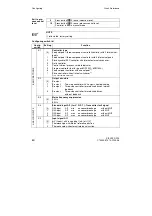
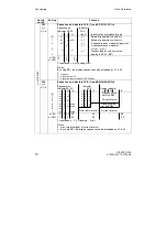
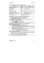
S85
Function of limit monitor A1/A2
[0]
1
2
A1 max / A2 min
A1 min / A2 min
A1 max / A2 max
S86
Function of limit monitor A3/A4
[0]
1
2
A3 max / A4 min
A3 min / A4 min
A3 max / A4 max
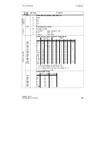
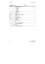
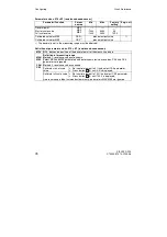
S87
Display and setting of limit values A1 to A4 in the process control
level
Indicator
Parameter
Signalling of violated limit
SP-W (2)
1)
adustable
values via L1 to L4
1)
[0]
1
2
3
4
5
6
no
no
A1/A2/A3/A4
no
no
A3/A4 (for S1= 05)
no
no
no (for S1=1 or 5)
A3/A4
no
A3/A4 (for S1=5)
A1/A2/A3/A4
no
A1/A2/A3/A4
A3/A
yes
A3/A4 (for S1=5)
A1/A2/A3/A4
yes
A1/A2/A3/A4
Note:
In switch positions 1,2,3 and 5 the lamps L1 and L2 are free for signalling
of program 1 or 2 running (with S1 = 5).
1)
In this case the parameter names are indicated with the frequency 0.5 by the
lamps L1 to L4. By pointed and addressed limit value the defined signal LED flash-
es with the frequency 0.9.
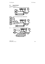
Config.
switch
Setting
Function
DI
GI
T
A
L
I
N
P
U
T
L
IM
IT M
O
N
ITO
R
S
Содержание SIPART DR19
Страница 2: ......
Страница 6: ...SIPART DR19 6 C73000 B7474 C140 06 Übersicht Kurzanleitung ...
Страница 50: ...SIPART DR19 50 C73000 B7474 C140 06 Overview Quick Reference ...
Страница 93: ......