


Connections
02.2001
SIMOLINK Pulse Generator
GWE-477 764 4070.76 J
Siemens AG
5-2
Operating Instructions
SIMOVERT MASTERDRIVES
5.2
Encoder interface X2
The encoder interface of the SIMOLINK Pulse Generator is the 9-pin,
SUB D socket with screw locking mechanism (UNC) on the front of the
housing. Two RS422 drivers each supply two signals per pulse output,
one signal with non-inverted signal level and one signal with inverted
signal level. The driver voltage supply circuit is isolated from the 24 V
supply for the module.
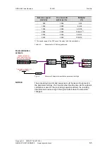
Frequency
generator
A+
A
−
B+
B
−
SEL_100 kHz
GND
P5
2
7
4
9
1
3,8
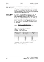
Fig. 5-2
Schematic of output circuit (connector X2)
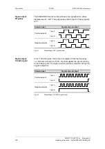
The two operating modes "90° pulses" and "100 kHz signal" are
selected via a jumper in the encoder connector. The 90° pulses setting
is the default and is activated when pin 1 in the encoder interface is
unused.
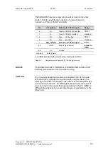
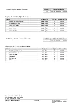
Pin
Signal
Meaning for 90° pulses
Range
2
A+
Track A not inverted
RS422
7
A–
Track A inverted
standard
4
B+
Track B not inverted
RS422
9
B–
Track B inverted
standard
1
SEL_100 kHz
Do not assign,
selection of 100-kHz signal
Do not
insert
3, 8
GND
Ground (see below)
jumper to
GND!
5, 6
n.c.
Unused
Housing
Outer shield
9-pin SUB D socket with screw locking mechanism (UNC)
Table 5-2
Assignment of connector X2 for 90° pulses mode


