SIMOLINK Pulse Generator
02.2001
Start-Up
Siemens AG
GWE-477 764 4070.76 J
SIMOVERT MASTERDRIVES
Operating Instructions
6-1
6 Start-Up
6.1
Setting the DIL switch
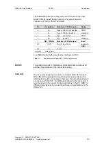
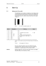
The SIMOLINK receive address (in dispatcher mode, address of the
node transmitting the speed setpoint to the SLP) for the SIMOLINK
Pulse Generator is set by means of an 8-channel DIL switch on the
front of the housing. The receive channel cannot be set; its default
setting is 0.
2
0
2
7
ON
CHANNEL
Fig. 6-1
DIL switch for read address (address =75)
Switch
Designation
Meaning
Range
.1
2
0
= 1
.2
(2
1
)
= 2
.3
(2
2
)
= 4
.4
(2
3
)
= 8
.5
(2
4
)
= 16
.6
(2
5
)
= 32
.7
(2
6
)
= 64
.8
2
7
C
hanne
l
=128
SIMOLINK receive address
Note:
Switch 1 is the least significant bit.
Switch position on right means "1“ or
"ON“.
0…200
Channel 1 of the DIL switch is at the top of the housing front panel in the assembled
state.
Table 6-1
Value assignments for DIL switch
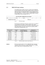
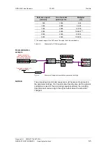
When set via the DIL switches, the receive address is directly
transferred and the setpoint contained in the receive telegram is
available as an output frequency at the encoder interface.
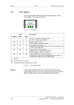
Address settings 201 to 255 are invalid, LEDs "SYNC“ and "FREQ“
flash alternately and no frequency is output.
NOTICE


