background image

5-1

SIMATIC Panel PC 870 Computing Unit,  Equipment Manual

Configuring the Computing Unit in BIOS
Setup

Chapter overview

This chapter explains how to configure the computer unit. You need to do this if
you want to change your system by adding, removing or exchanging an
extension board, memory expansion module or by replacing a system module.

In Section

You Will Find

On Page

5.1

Modifying the device configuration with BIOS SETUP

5-2

5.2

Main menu

5-5

5.3

Advanced menu

5-12

5.4

Security menu

5-18

5.5

Power menu

5-20

5.6

Boot Sequence menu

5-22

5.7

Version menu

5-24

5.8

Exit menu

5-25

5.9

BIOS setup default settings

5-26

5

Содержание Simatic PC Panel PC 870

Страница 1: ... the Computing Unit 4 Configuring the Computing Unit in BIOS Setup 5 Fault Diagnosis 6 Hardware Information 7 Decentralized Design 8 Appendices A B Glossary Index Release 11 02 Panel PC 870 Computing Unit Equipment Manual SIMATIC PC This manual is valid for computer units with order numbers 6AV770x xC 6AV771x xC 6AV770x xD and 6AV771x xD ...

Страница 2: ...d personnel within the meaning of the safety notices in this manual are persons who are authorized to commission ground and identify equipment systems and circuits in accordance with safety engineering standards Correct Usage Note the following Warning The equipment may be used only for the applications stipulated in the catalog and in the technical descrip tion and only in conjunction with other ...

Страница 3: ...e cannot guarantee full agreement However the data in this manual are reviewed regularly and any necessary corrections included in subsequent editions Suggestions for improvement are welcomed Disclaimer of Liability Copyright Siemens AG 2002 All rights reserved The reproduction transmission or use of this document or its contents is not permitted without express written authority Offenders will be...

Страница 4: ...Chapter For your notes ...

Страница 5: ...nsion options for the computer unit on the configuration error diagnostics and the hardware S SIMATIC Panel PC 670 870 Operating Unit Equipment Manual The equipment manual contains information on operating the operating unit error diagnostics and the hardware S SIMATIC Panel PC 670 870 Installation Guide This Installation Guide contains the information on the mechanical and electrical installation...

Страница 6: ...C Names of keys and buttons are shown in a different type face History Release Comments 07 01 Initial release of the SIMATIC Panel PC 870 Computer Unit equipment manual 12 01 Addition of the Decentralized Design option to the SIMATIC Panel PC 870 Computer Unit Equipment Manual 11 02 Technical update to the SIMATIC Panel PC 870 Computer Unit equipment manual Trademarks The following designations ar...

Страница 7: ... 895 7001 GMT 01 00 Europe Africa Nuremberg Authorization Local time Mon Fri 8 00 to 17 00 Telephone 49 911 895 7200 Fax 49 911 895 7201 E Mail authorization nbgm siemens de GMT 1 00 America Johnson City Technical Support and Authorization Local time Mon Fri 8 00 to 19 00 Telephone 1 423 461 2522 Fax 1 423 461 2289 E Mail simatic hotline sea siemens com GMT 5 00 Asia Australia Singapore Technical ...

Страница 8: ...om automation service support Training Center Siemens offers a number of training courses to familiarize you with the SIMATIC S7 automation system Please contact your regional training center or our central training center in D 90327 Nuremberg Germany for details Telephone 49 911 895 3200 Internet http www sitrain com E Mail info sitrain com Other Sources of Assistance In case of technical queries...

Страница 9: ... 3 Drives with Interchangeable Media 3 7 3 3 1 Floppy disk drive 3 7 3 3 2 CD ROM or CD RW DVD drive according to device configuration 3 8 3 4 Reset Button 3 10 4 Servicing and Expanding the Computing Unit 4 1 4 1 Opening the Device 4 2 4 1 1 Requirements 4 2 4 1 2 Opening the computer unit 4 3 4 1 3 Functional units visible after opening the device 4 4 4 1 4 Motherboard 4 5 4 2 Installing and Rem...

Страница 10: ...ules 6 2 6 2 Operating Unit Display Remains Dark 6 3 6 3 System Time and or Date of the PC Incorrect 6 3 6 4 Error Message Appears on the Screen Display 6 4 6 5 Computer Unit Self test Prior to Booting 6 6 7 Hardware Information 7 1 7 1 Spare Parts and Accessories 7 2 7 1 1 Spare parts 7 2 7 1 2 Accessories 7 2 7 2 Overview of Components and Interfaces 7 3 7 3 System Resources 7 4 7 4 Monitoring F...

Страница 11: ... Decentralized Design 8 1 8 1 Description 8 2 8 1 1 Overview 8 2 8 1 2 Dimensions 8 3 8 1 3 Mounting 8 3 8 2 Cable Connections 8 4 8 3 Spare Parts 8 4 8 4 Technical Data 8 5 A Technical Data A 1 B ESD Guidelines B 1 B 1 What Does ESD Mean B 2 B 2 Electrostatic Charge of People B 3 B 3 Additional safety measures against discharges of static electricity B 3 Glossary Glossary 1 Index Index 1 ...

Страница 12: ...Contents Release 11 02 xii SIMATIC Panel PC 870 Computing Unit Equipment Manual ...

Страница 13: ...ipment Manual Product Overview Chapter Overview In Section You Will Find On Page 1 1 Advantages of the computer unit 1 2 1 2 Safety notes 1 5 1 3 Certificates guidelines and declarations 1 9 1 4 Certification for USA Canada and Australia 1 11 1 ...

Страница 14: ...characterized by S extensive climatic vibration and shock tests to ensure industrial compatibility S electromagnetic compatibility conforming to CE and FCC S UL CSA approvals S user support by hotline service spare parts S quality assurance conforming to ISO 9001 S compliance with the requirements for a fire enclosure to EN60950 UL1950 in other words it may be used without an additional fire enclo...

Страница 15: ...e and inclined at an angle of up to 70 for example in a swivel arm boom or console The more sensitive computer unit hard disk can be installed vertically some distance away from the machine where vibration is low for example in a cabinet With this configuration additional components are included for communication between the operating unit and computer unit the host module which is mounted on the ...

Страница 16: ...n the computer unit can be used virtually anywhere S The computer unit includes all ports and interfaces required for automation with SIMATIC These particularly relate to Parallel port LPT 1 Serial ports 1x V 24 1x V 24 TTY PS 2 keyboard port supports PG720 740 keyboard with trackball PS 2 mouse port USB port 2x external MPI Profibus DP max 12 MBaud Ethernet interface 10 100 MBaud RJ45 VGA interfa...

Страница 17: ...ating location from a cold environment condensation may occur Before starting up the device must be dry and therefore an acclimatization period of at least 12 hours is necessary Before installing and operating the device please note the information on ambient conditions in the Appendix A Technical Data and on installing the device in Chapter 2 The device must be installed in such a way that it pre...

Страница 18: ... rated voltage for the device coincides with that of the local mains voltage This device is equipped with a safety tested power supply cable and may be connected only to a socket outlet with grounding contact Make sure that the socket outlet on the device or the socket outlet with grounding contact of the building wiring system is freely accessible and located as near to the device as possible To ...

Страница 19: ... conductor cross section at least 18 to AWG and grounding type plug 15 A 250 V Make sure that the cable set complies with the safety standards of the country where the devices will be installed and that they bear the relevant markings Repairs Repairs to the SIMATIC Panel PC 870 may only be carried out by authorized adequately trained personnel Warning Unauthorized opening and repairs to devices ca...

Страница 20: ...f used batteries according to the applicable laws or manufactuer s information ESD guidelines Components containing ESD Electrostatically Sensitive Devices may be identified by the following label When handling components containing ESD it is essential to observe the following guidelines S Before working with components containing ESD you must discharge any static electricity from your body e g by...

Страница 21: ...EN 50082 1 1992 Industrial sector EN 50081 2 1993 EN 50082 2 1995 The standards EN 61000 3 2 1995 harmonic currents and EN 61000 3 3 1995 voltage fluctuations and flicker are also maintained Direct current DC power supply The units with a direct current AC power supply fulfill the requirements of EU Guideline 89 336 EEC Electromagnetic Compatibility and are designed for use in the following sector...

Страница 22: ... must be observed when starting up and operating the system Connection of periphery devices The requirements concerning interference immunity are met when periphery equipment suitable for industrial demands is connected in accordance with EN50082 2 1995 Periphery devices may only be connected using shielded cables DIN ISO 9001 certificate The quality assurance system of our entire product producti...

Страница 23: ...with Canadian Standard C22 2 No 950 I T E or complying with C22 2 No 142 IND CONT EQ Underwriters Laboratories UL complying with Standard UL 1950 Report E11 5352 and Canadian Standard C22 2 No 950 I T E or complying with UL508 and C22 2 No 142 IND CONT EQ or complying with UL508 and C22 2 No 142 IND CONT EQ UL Recognition Mark Canadian Standard Association CSA complying with Standard C22 2 No 950 ...

Страница 24: ...elded cables must be used with this equipment to maintain compliance with FCC regu lations Modifications Changes or modifications not expressly approved by the manufacturer could void the user s authority to operate the equipment Conditions of Operations This device complies with Part 15 of the FCC Rules Operation is subject to the following two conditions 1 this device may not cause harmful inter...

Страница 25: ...el PC 870 Computing Unit Equipment Manual Starting Up the Computing Unit Chapter overview In Section You Will Find On Page 2 1 Unpacking and checking the items delivered 2 2 2 2 Ensuring readiness for operation 2 3 2 ...

Страница 26: ...s When doing so you should also take into observe accessories which you can order separately 6 Should you detect any transport damages or inconsistencies between packaging contents and packaging list please inform your sales office Recording the serial number SVP number 7 Record the serial number SVP number of the computer unit in the table the number is located on the rating plate above the flopp...

Страница 27: ...with regard to the power supply and the equipotential bonding Since the computer unit does not possess a mains switch it will be ready for service immediately after the mains plug has been connected Power supply Socket connector for AC powered non heating ap pliances with DC powered devices a screw type terminal as an option Equipotential bonding connection Figure 2 1 Power supply connection The A...

Страница 28: ...isconnecting I O devices keyboard mouse printer etc Failure to do so can result in damage to the computer unit A connector safety interlock is supplied with a 120 V 230 V power supply Caution The computer unit with AC power supply is equipped with a safety tested mains cable and may only be connected to a grounding outlet Make sure that the outlet on the device or the grounding outlet socket of th...

Страница 29: ...ipment Manual Connecting and Operating the Computing Unit Chapter Overview In Section You Will Find On Page 3 1 Ports interfaces and connections 3 2 3 2 Connecting I O devices 3 6 3 3 Drives with interchangeable media 3 7 3 4 Reset button 3 10 3 ...

Страница 30: ...grams and data to floppy disks and load from floppy disks into the PC 870 2 COM1 V 24 MODEM PLC 1 S5 automation units PLCs for example can be connected via the COM 1 TTY interface 3 MPI DP Multipoint Interface 2 You can connect the PC 870 either to an S7 PLC or a PROFIBUS network via the floating MPI DP interface 4 Ethernet RJ 45 Ethernet connection The Ethernet is a local network with bus structu...

Страница 31: ...t configuration in the BIOS SETUP submenu Hardware Options parameter CRT LCD selection see Chapter 5 12 PCI slots Internal slots for PCI expansion modules 13 PCI ISA slots Internal slots for expansion modules 14 ISA slot Internal slot for an ISA expansion slot 15 CD ROM drive piggyback version option Using the CD ROM drive you can read data from CD ROM If expansion modules are plugged in the compu...

Страница 32: ...unit You will thus improve the electrical shielding Note Additional information on decentralized design is available in Chapter 8 Connections Function COM1 V24 AG By plugging the adapter plug supplied as accessories Gender Changer you will change the connection into a socket connec tor MPI DP RS 485 Equipotential bonding within the safety extra low voltage circuit SELV If expansion modules are plu...

Страница 33: ...cable to the printer 4 Tighten screw the connector on the port LPT 1 socket connector parallel COM 2 connector serial COM 1 socket connector serial USB port Figure 3 2 Printer connection Caution Connect printers to the parallel port only when the device on the LPT 1 port is turned off printer likewise turned off Ensure to use the correct port If connectors are interchanged or the wrong connecting ...

Страница 34: ...e you should use in the user manual for your printer 3 2 3 Connecting USB devices Devices equipped with a USB interface can be connected to the USB interface see Fig 3 2 without interrupting the power supply S Plug in the USB cable The device is detected automatically by a plug and play operating system such as Windows 98 and is then available A USB keyboard can be operated to run BIOS setup Note ...

Страница 35: ...s into the computer unit Floppy disk drive Figure 3 3 Floppy disk drive Floppy disk types With the floppy disk drive you can use the following floppy disks Double Sided High Density 3 5 in 1 44 MB 135TPI Floppy disk handling with floppy disk drive Insert the floppy disks into the drive as illustrated depending on the installation location Access light Ejector Ejector Access light Figure 3 4 Disket...

Страница 36: ...ution Danger of data being lost and the drive damaged CD ROM and CD RW DVD drives are very sensitive to vibration during operation vibration could cause damage to the drive and or data medium For permissible values refer to Appendix B Note After closing the tray first the CD is tested and the access light on the drive starts flashing flashes continuously bad but still readable CD is lit continuous...

Страница 37: ...re sensitive to unacceptable vibration During operation vibrations might damage the drive and or the data medium To operate the CD DVD drive in CD write mode the ambient temperature must be between 5_C and 40_C Constant operation of the CD drive in write mode is not permitted because the writer and media are not designed for continuous use Additional software In order to exploit the full functiona...

Страница 38: ...ton on your device will initiate a hardware reset this will restart your PC cold restart In the case of the SIMATIC Panel PC 870 the Reset button is to be found on the interface side between the PS 2 sockets The Reset button can only be actuated with a pointed object e g ballpoint pin or a paper clip bent open Reset button Figure 3 6 Reset button ...

Страница 39: ...eed when installing expansions Please observe the safety notes it contains In Section You Will Find On Page 4 1 Opening the device 4 2 4 2 Installing and removing drives 4 7 4 3 Installing and removing expansion boards 4 11 4 4 Installing and removing the power supply 4 13 4 5 Installing and removing the device fan 4 15 4 6 Installing and removing the backup battery 4 15 4 7 Installing and removin...

Страница 40: ...ion modules approved by SIEMENS No liability can be accepted for impairment of functions caused by the use of non Siemens devices or non Siemens components All the modules and components are electrostatically sensitive Please study the notes on electrostatic sensitive devices see Appendix The following symbol indicates that electrostatically sensitive modules are present Tools You can perform all ...

Страница 41: ...ted conductors S Never operate the device with the cover open 4 1 2 Opening the computer unit Proceed as follows to open the computer unit 1 Disconnect the power connector then all connection cables and interconnection cables from the device including the keyboard cable 2 Remove the computer unit from its mounting cabinet only necessary if mounting screws are inaccessible as a result of installati...

Страница 42: ...Unit Equipment Manual 4 1 3 Functional units visible after opening the device Once you have removed the top cover of your unit the functional units are visible Bus board Floppy disk drive Power supply Fan Backup battery Processor Slots for memory ex pansion Figure 4 2 Computer unit opened View ...

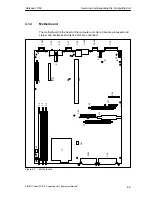
Страница 43: ...uipment Manual 4 1 4 Motherboard The motherboard is the heart of the computer unit Here data are processed and stored and interfaces and device I Os are controlled X22 S1 X23 X31 X36 X700 X400 X30 X34 X33 X20 X25 X12 X26 X50 X10 X7 X41 X44 X300 X1 X3 X4 X5 X49 X42 X28 X29 X303 Figure 4 3 Motherboard ...

Страница 44: ...PS 2 mouse X23 PS 2 keyboard X25 Connection for 1 44 MB slimline floppy X26 Connection for standard floppy X28 Internal socket connector for COM1 V 24 TTY module X29 Internal socket connector for COM1 V 24 TTY module X30 Serial interface COM1 TTY X31 Serial interface COM2 X33 COM2 internal for touch screen X34 Parallel interface LPT 1 X36 USB port X42 Device fan connection X41 Processor fan X44 I ...

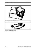
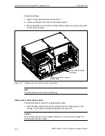
Страница 45: ...ng operation vibrations can result in a loss of data or damage to the drive or a data medium If you wish to ship the device wait until the drive has come to rest after you turn off the device approximately 20 s Proceed as follows see Fig 4 4 1 Loosen the 4 screws on the back of the system housing 2 Swing open the drive cage 3 Detach the drive cage from its mounting and place the drive cage face do...

Страница 46: ...ng and Expanding the Computing Unit Release 11 02 4 8 SIMATIC Panel PC 870 Computing Unit Equipment Manual Fixing screws Figure 4 4 Removing and installing the drive cage Figure 4 5 Hard disk with cage removed ...

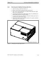
Страница 47: ...detach the data and power supply cables from the floppy disk drive 4 Loosen the interlocking of the controller flexible cable on the motherboard and pull the flexible cable out of the plug connection 5 Loosen the two fixing screws TORX T8 on the system housing see Fig 4 6 and lift the drive cage out of the housing 6 Proceed in the reverse order to install the new drive The new drive must be of the...

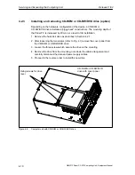
Страница 48: ...t of its installation 1 Remove the hard disk drive as described in Section 4 2 1 2 After loosening the two screws refer to Fig 4 7 remove the cover panel from the CD ROM or CD RW DVD drive 3 Loosen the three screws which secure the drive on the mounting 4 Remove the drive from the mounting note down the cable arrangement and carefully disconnect the data and power supply cables 5 Proceed in the re...

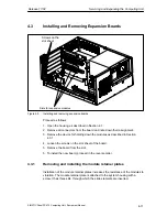
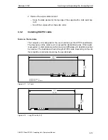
Страница 49: ... from the board and note down their assignment 3 Remove the device for holding down the modules as described in Section 4 3 1 4 Loosen the screws on the slot sheet of the board 5 Remove the board from the slot 6 To install the new board proceed in the reverse order 4 3 1 Removing and installing the module retainer plates Installation of the module retainer plates increases the resistance of the mo...

Страница 50: ...ousing Guide slits for slide elements Fixing screws for the module retainer plate Figure 4 10 Installing and removing the module retainer plate Note The slide elements are in the enclosed bag Aligning the module retainer plate Proceed as follows to install the module retainer plate 1 Insert the slide element through the guide slit until it is resting firmly on the module The module must now be int...

Страница 51: ...ter unit is designed for the use of cards as per the AT PCI specification The dimensions of the cards must not exceed the stated dimensions If the height is exceeded contact problems malfunctions and difficulties with installation cannot be ruled out The illustrations show full length AT PCI cards Depending on the slot there might be constraints concerning the overall length 340 7 121 92 A31 A1 Al...

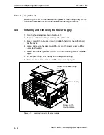
Страница 52: ...1 2 Remove the drive mounting as described in section 4 2 1 3 Make a note of the cable assignment and detach them from the motherboard and the drives 4 Loosen and remove the six screws of the cover of the power supply unit from the system housing 5 Loosen the three fixing screws TORX T10 on the mounting plate of the power supply 6 Pull the power supply unit laterally out of the system housing 7 Pr...

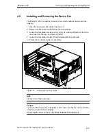
Страница 53: ...board 3 Loosen the four plastic rivets see Fig 4 14 by pushing off the arbor from the rivet body from the rear and remove the fan 4 Loosen the four plastic rivets of the sheet plate with the guide rails 5 Proceed in the reverse order for assembly Plastic rivets Figure 4 14 Installing and removing the fan Note Fit only a fan of the same type Caution To ensure that the device is adequately cooled ta...

Страница 54: ...placed Changing the battery Proceed as follows 1 Disconnect the device from the mains and remove all interconnecting cables 2 Open the device as described in Section 4 1 3 Change the backup battery by removing the connector from base X49 of the motherboard see Fig 4 3 and remove the battery from its holder 4 Attach the new battery in its holder and connect the battery connector to the motherboard ...

Страница 55: ...rboard or bus board must only be carried out by authorized service personnel 4 8 Installing a Memory Expansion Enhance the functionality of the computer unit by installing additional main memory To do so please observe the relevant safety notes Standard memory Three slots for 144 pin SDRAM memory modules are provided on the motherboard enabling you to expand the user memory of your computer unit u...

Страница 56: ... SDRAM modules Proceed as follows to plug the modules in 1 First open the device as described in Section 4 1 2 Plug the modules into the socket Please observe the recess anti rotation element on the connector side of the SDRAM module 3 Push the module down exerting slight pressure on it until the locking snaps into place 4 Close the device Caution Risk of damage Make sure that the modules fit tigh...

Страница 57: ... change your system by adding removing or exchanging an extension board memory expansion module or by replacing a system module In Section You Will Find On Page 5 1 Modifying the device configuration with BIOS SETUP 5 2 5 2 Main menu 5 5 5 3 Advanced menu 5 12 5 4 Security menu 5 18 5 5 Power menu 5 20 5 6 Boot Sequence menu 5 22 5 7 Version menu 5 24 5 8 Exit menu 5 25 5 9 BIOS setup default sett...

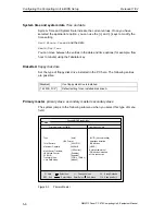
Страница 58: ...ETUP to define the hardware configuration e g hard disk type and system properties Setup is also used to set the system date and time on the clock module Incorrect BIOS data If incorrect BIOS data is detected during the boot routine the prompts BIOS the user to S start BIOS SETUP by pressing F2 or S continue booting by pressing F1 Starting BIOS SETUP On completion of the startup test the BIOS give...

Страница 59: ...M Passed 0256K Cache SRAM Passed System BIOS shadowed Video BIOS shadowed Mouse initialized Fixed Disk 0 xxxx ATAPI CD ROM Txxx Press to enter SETUP By pressing the F2 key when the above figure is displayed the system switches to the ROM based BIOS Setup program In this program you can set a number of system functions and hardware configurations of your programming device The default settings are ...

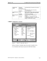
Страница 60: ... Menu Example The screen is divided into four sections In the top section you can select the menu screens Main Advanced Security Power Boot Sequence Version Exit In the left of center section you can choose the different settings or submenus Brief help texts appear on the right for the currently selected menu entry The bottom section contains information for operator inputs Yellow stars to the lef...

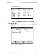
Страница 61: ...512 KB Example Hour Minute Second Month Day Year Boot Sequence Version F1 Help Memory Cache WriteBack Figure 5 2 SETUP Main Menu Settings in the main menu In the Main menu you can move upwards and downwards using the cursor keys and to select the following system parameters Field Meaning System Time For viewing and setting the current time System Date For viewing and setting the current date Diske...

Страница 62: ...es are possible Disabled If no floppy disk drive is installed 1 44 MB 31 2 Default setting for an installed disk drive A Primary master primary slave secondary master secondary slave The system jumps to the following submenu when you select this type of menu field PhoenixBIOS Setup Utility Item Specific Help ESC Exit Select Item Select Menu Enter Select Change Values F9 F10 Setup Defaults Save and...

Страница 63: ... set according to the hard disk type Multi Sector Transfer Field The entry in the Multi Sector Transfers field defines the number of blocks sectors transferred per interrupt The value depends on the drive and should only be set by setting the Type field to Auto Disabled 2 4 8 16 sectors LBA Mode Control If the LBA Mode Control field enabled disabled is set to Enabled the system supports hard disks...

Страница 64: ... 4 Boot Options submenu Quick Boot Mode Some hardware tests are skipped when the system starts up thus speeding up the boot procedure SETUP prompt The message PRESS F2 to enter Setup appears at the bottom of the screen during the system load phase POST Errors The boot process is stopped if an error is detected you must press F1 to acknowledge Enter Disabled to avoid the necessity of acknowledging ...

Страница 65: ...C 840 BIOS Version V10 01 02 Pentium PII Hard Disk 2 Hard Disk 3 None None Figure 5 5 Summary Screen The Summary screen appears when the system run up phase completes Keyboard Features field The following submenu appears after selecting the Keyboard Features field in the main menu PhoenixBIOS Setup Utility Item Specific Help ESC Exit Select Item Select Menu Enter Select Change Values F9 F10 Setup ...

Страница 66: ...int Interface MPI DP PS 2 Mouse Enabled CRT LCD selection SIMULTAN LCD Screensize Graph Text Expand F1 Help Ethernet Address 080006247000 On Board Ethernet Enabled Legacy USB Support Disabled LAN Remote Boot Enabled SafeCard functions Enabled Fan Control Enabled Figure 5 7 Hardware Options submenu The parameters of the interfaces present on the basic module are set here Entry Meaning PCI MPI DP En...

Страница 67: ...e is disabled CRT Enabled For maximum resolution the display signals are only sent to the 15 pin VGA interface the LCD interface of the VGA controller is disabled SIMULTAN Both display interfaces are enabled and operate simultaneously However not al resolutions are possible on the LCD LCD screen size Normal The display window in Text and Graphic modes is not expanded to full screen size Text expan...

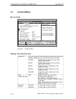
Страница 68: ...this menu to incorrect values may cause your system to malfunction Figure 5 8 Advanced Menu Settings in the Advanced menu Installed O S Plug and Play means that all modules are automatically detected and installed providing they support the Plug and Play functionality OTHER The BIOS assumes the entire Plug and Play capability default setting Win95 The BIOS assumes the entire Plug and Play capabili...

Страница 69: ...ned to additional ISA modules COM LPT Configuration submenu PhoenixBIOS Setup Utility Item Specific Help ESC Exit Select Item Select Menu Enter Select Change Values F9 F10 Setup Defaults Save and Exit Sub Menu Base I O address Enabled Interrupt IRQ 4 Internal COM 1 COM LPT Configuration Configure internal COM port using options Disabled No configuration Enabled User configuration Auto BIOS or OS c...

Страница 70: ...ctional SPP S Standard setting for the 8 bit parallel transfer according to IEEE1284 specifications S Feedback of the output device is only possible via the control cables Bidirectional Standard parallel port bidirectional as for SPP unidirectional however S Feedback of the output device is also possible via the 8 bit data cables EPP Enhanced parallel port S Enhanced parallel port data transfer ra...

Страница 71: ...to Select Auto Select Auto Select F1 Help Setup items for configuring the specific PCI device Advanced PCI Device Slot 1 PCI Device Slot 2 PCI Device Slot 3 PCI Device Slot 4 Figure 5 10 PCI Configuration submenu PCI Devices submenu If the PCI devices field is selected the following submenu appears PhoenixBIOS Setup Utility Item Specific Help F1 ESC Help Exit Select Item Select Menu Enter Select C...

Страница 72: ...t to the selected values 00E0H PCI PNP ISA IRQ Resource Exclusion submenu Available means that the BIOS Plug and Plug device can assign IRQs to Plug and Play compatible modules or main board functions Reserved should only be set when the interrupt in question must be assigned to non Plug and Play capable modules PhoenixBIOS Setup Utility Item Specific Help ESC Exit Select Item Select Menu Enter Se...

Страница 73: ...bled Auto Select 3 4 5 7 9 10 11 12 14 15 F1 Help Advanced Figure 5 13 PCI Configuration submenu Disabled No interrupt possible for this PCI IRQ line AutoSelect Plug and Play mechanism in BIOS selects unassigned interrupts and allocates them to the on board PCI devices 3 to 15 The PCI IRQ line is assigned to the selected interrupt Do not use this setting unless it is specifically required in your ...

Страница 74: ...utility Figure 5 14 Security Menu User Password is Disabled Password is active BIOS Setup can only be opened after entering the password Enabled Certain Setup fields can be modified by the user including the user password The input field automatically changes from Disabled to Enabled when the password is entered Set Supervisor Password This field opens the dialog box for entering a password Once i...

Страница 75: ...led Supervisor Diskette access is not possible unless the supervisor password was entered during system boot User Diskette access is not possible unless the user password was entered during system boot Attention This function cannot be used under Windows NT 2000 XP since this operating system does not access the diskette via BIOS routines Please use the system programs provided by Windows NT 2000 ...

Страница 76: ...e Exit Boot Sequence Version F1 Help Figure 5 15 Power Save menu The Power Save menu offers a number of power saver modes for environmentally friendly computing APM Advanced Power Management Enabled The operating system can shut down system resources when they are not needed Disabled The operating system is denied APM access Power Savings Disabled No power saving functions Customize Maximum Power ...

Страница 77: ...ting Unit Equipment Manual Hard Disk Timeout Disabled The hard disk does not shut down 10 15 30 60 Time since the last hard disk access the hard disk is shut down On the next access the hard disk will be activated again with a short delay Can only be set if Power Savings is set to Customized ...

Страница 78: ...evice up or down Ctrl Enter expands all Sub Menu Main Security Power Advanced Diskette Drive Removable Device Hard Drive ATAPI CD ROM Drive Intel Boot Agent Exit Version F1 Help Figure 5 16 Boot Sequence menu This menu lists the boot devices in groups The group with the highest priority is at the top The procedure for changing the sequence is as follows Use the keys to select a group and the or ke...

Страница 79: ... view or configure devi ces Enter expands or collapses devices with a or Ctrl Enter expands all and moves the device up or down Sub Menu Main Security Power Advanced Diskette Drive Floppy Drive Removable Devices Floppy Drive Hard Drive IFUJITSU MPD3043AT PM Alternate Device ATAPI CD ROM Drive Intel Boot Agent Exit Version F1 Help Figure 5 17 Boot Sequence menu This screen shows all possible boot d...

Страница 80: ...tup Utility Item Specific Help ESC Exit Select Item Select Menu Enter Select Change Values F9 F10 Setup Defaults Save and Exit All items on this menu cannot be mo dified in user mode If any items re quire changes please consult your system supervisor Sub Menu Main Security Power Advanced SIMATIC Exit Version Box PC 840 BIOS Version V7 BIOS Number A5E000xxxxx ES0x MPI DP Firmware V01 CPU Type Dixon...

Страница 81: ...changes to CMOS Sub Menu Save Changes Exit Exit Without Saving Changes Get Default Values Load Previous Values Save Changes Main Security Power Advanced Exit Boot Sequence Version F1 Help Figure 5 19 Exit menu Save Changes Exit All changes are saved a system restart is carried out with the new parameters Discard Changes Exit All changes are rejected a system restart is carried out with the old par...

Страница 82: ...ult Settings Your Entries Main System Time hh mm ss System Date MM DD YYYY Diskette A 1 44 MB 31 2 Primary Master C 6495 MB Primary Slave None Secondary Master None Secondary Slave None Boot Options Quick Boot Mode Enabled SETUP prompt Enabled POST Errors Enabled Floppy check Disabled Summary screen Enabled Keyboard Features Num Lock On Key Click Disabled Keyboard auto repeat rate 30 s Keyboard au...

Страница 83: ...CI Device Slot 2 Option ROM Scan Enabled Enable Master Enabled Latency timer 0040 h on board PCI Ethernet Option ROM Scan Disabled Enable Master Disabled Latency timer 0040 h PCI PnP ISA IRQ Exclusion IRQ3 Available IRQ4 Available IRQ5 Available IRQ9 Available IRQ10 Available IRQ11 Reserved PCI IRQ Line 1 Auto Select PCI IRQ Line 2 Auto Select PCI IRQ Line 3 Auto Select PCI IRQ Line 4 Auto Select ...

Страница 84: ...n boot Disabled Fixed disk boot sector Normal Diskette Access Supervisor Power APM Enabled Power Savings Disabled Standby Timeout off Suspend Timeout off Hard Disk Timeout Disabled Boot Sequence Diskette Drive Removable Devices Hard Drive ATAPI CD ROM Drive Intel Boot Agent Version SIMATIC Box PC 840 BIOS Version V7 xx BIOS Number A5E16562 ESxx MPI DP Firmware V01 CPU Type Dixon CPU Speed 266 MHz ...

Страница 85: ... documentation of your operating system S This manual contains error messages that occur during the self test screen messages sound sequences in the Sections 6 4 and 6 5 In Section You Will Find On Page 6 1 Problems when using non Siemens modules 6 2 6 2 Operating Unit Display Remains Dark 6 3 6 3 System time and or date of the PC incorrect 6 3 6 4 Error message appears on the screen display 6 4 6...

Страница 86: ...r pin assignment other than specified Remedy Check the configuration of your PC S If the configuration of your PC corresponds to the works default settings please contact your technical service department S If the configuration of your PC has been changed restore the default status to do so remove all non Siemens modules and then restart the computer If the problem persists call the hotline If the...

Страница 87: ...ule is not correct S The necessary DIP switch settings for a decentralized 12 or 15 display are indicated on the inner side of the housing of the host module Note For further information please refer to the Start up Guide 6 3 System Time and or Date of the PC Incorrect Remedy Use the Setup menu to set system time and or date see Chapter 5 While the computer is booting press to call the setup Note ...

Страница 88: ...stem battery is dead Replace and run SETUP The battery on the CPU module is defective or empty Change the battery as described in Section 4 6 System CMOS checksum bad Run SETUP Call SETUP see Chapter 5 define and save settings If this mes sage always occurs whenever the PC boots contact the technical customer service Incorrect Drive A type Run SETUP Check the SETUP entries of drive A Incorrect Dri...

Страница 89: ...has been terminated e g due to mains power failure Correct entries in SETUP see Chapter 5 System cache error Cache disabled Error of the cache module of the CPU module Contact the technical customer service Monitor type does not match CMOS Run SETUP Monitor does not match the SETUP entries see Chapter 5 Match the SETUP entries with the monitor System timer error Hardware error Contact the technica...

Страница 90: ...the POST the appropriate sound sequence beep code corresponding to the POST is output The beep code consists of 2 x 2 sequences each Conversion table of the beep codes using the hexadecimal representation Beep Tones Hex Code B B 0 B BB 1 B BBB 2 B BBBB 3 BB B 4 BB BB 5 BB BBB 6 BB BBBB 7 BBB B 8 BBB BB 9 BBB BBB A BBB BBBB B BBBB B C BBBB BB D BBBB BBB E BBBB BBBB F Example B BBBB BBB BBB Sound Se...

Страница 91: ...NIT Initialize cache 16 TP_CHECKSUM EPROM checksum test 28 TP_SIZE_RAM Determine the RAM size 3 A TP_CACHE_AUTO Determine the cache size 2A TP_ZERO_BASE Set 512k base RAM to 0 2C TP_ADDR_TEST Test the base RAM address cables 2E TP_BASERAML Basis RAM check 1st 64k 38 TP_SYS_SHADOW BIOS Shadow 20 TP_REFRESH Refresh block test 29 TP_PMM_INIT Initialize post memory manager 33 TP_PDM_INIT Initialize di...

Страница 92: ... setting 5C TP_MEMORY_TEST Test system memory 60 TP_EXT_MEMORY Test extended memory 62 TP_EXT_ADDR Test A20 address line 64 TP_USERPATCH1 Entry for your own initializations 66 TP_CACHE_ADVNCD Determine and enable the cache size 68 TP_CACHE_CONFIG Configure and test cache 6A TP_DISP_CACHE Display the cache configuration 6C TP_DISP_SHADOWS Display Shadow configuration and size Display RAM 6E TP_DISP...

Страница 93: ...r manager C3 TP_PEM_DISPLAY Display errors if any A8 TP_ERASE_F2 Clear F2 message AA TP_SCAN_FOR_F2 Was F2 pressed AC TP_SETUP_CHEK If necessary Switch F1 F2 message AE TP_CLEAR_BOOT Clear self test flag B0 TP_ERROR_CHECK Check for errors B2 TP_POST_DONE End of self test BE TP_CLEAR_SCREEN Clear screen B6 TP_PASSWORD Password query option BC TP_PARITY Cancel the parity flag BD TP_BOOT_MENU Display...

Страница 94: ...Fault Diagnosis Release 11 02 6 10 SIMATIC Panel PC 870 Computing Unit Equipment Manual ...

Страница 95: ...age 7 1 Spare parts and accessories 7 2 7 2 Overview of components and interfaces 7 3 7 3 System resources 7 4 7 4 Monitoring functions 7 5 7 5 Interfaces 7 7 7 6 Bus board 7 26 7 7 Alternating current power supply AC 7 33 7 8 Direct current power supply DC 7 34 7 9 Current requirement of the components maximum values 7 35 7 ...

Страница 96: ...or component from your Siemens branch office after you have specified the order number MLFB of your complete device Note Any further components not listed below such as processor motherboard or bus board must only be installed removed by authorized service personnel 7 1 1 Spare parts Spare parts see Chapter 4 are S Hard disk module and CD ROM CD RW DVD hard disk module S Floppy disk drive S Power ...

Страница 97: ... graphics memory S CRT up to 65535 colors or up to 256 colors Hard disk ATA 33 mode S Ultra DMA capable CDROM Master on secondary EIDE channel S 24 speed CD RW DVD Master on secondary EIDE channel Multi Spin Writer Drive S Read CD ROM CD R 14 32 times CD RW 8 20 times speed DVD 8 times S Write CD R 12 times CD RW 10 times Speed supports recording S Disc at once Track at once Session at once Packet...

Страница 98: ... system resources hardware addresses memory mapping interrupt assignment DMA channels are specified by the Windows operating system dynamically depending on the hardware equipment the drivers and connected external devices For the current assignment of the system resources or any conflicts refer to the following menus Windows 2000 XP Start Settings Control Panel Administrative Tools Computer Manag...

Страница 99: ...isplay Temperature monitoring The temperature is acquired by three sensors One sensor monitors the processor temperature the second monitors the temperature in the processor module area and the expansion boards while the third monitors the temperature in the drive area If one of the three temperature values exceeds the set temperature threshold an interrupt is triggered starting an action paramete...

Страница 100: ...dle when you turn on the computer unit or following a HW RESET cold restart in other words no reaction by the WD is initiated WD reactions If the WD is not retriggered within the set time by driver or SOM program the following reactions are triggered Reaction Option Acknowledge WD Initiate reset on the computer unit adjustable Send IRQ on computer unit adjustable SOM application is displayed adjus...

Страница 101: ...orts are described in the sections below 7 5 1 External ports Interface Position Connec tor Description COM 1 external X30 25 pin socket V 24 V 28 and 20mA TTY isolated COM 2 external X31 9 pin standard connector LPT1 external 25 pin standard socket PS 2 mouse external X22 6 pin mini DIN socket PS 2 keyboard external X23 6 pin mini DIN socket USB external X36 First and second USB port additionally...

Страница 102: ... Ground reference potential 8 DCD M5 Data Carrier Detect carrier Input 9 TTY RxD TTY Receive Input 10 17 NC Not Connected 18 TTY TxD TTY Send Output 19 20 mA Isolated power supply 13 25 20 DTR S1 Data Terminal Equipment Ready Output 21 TTY TxD TTY Send Output 22 RI M3 Incoming call Input 23 25 NC Not Connected Gender changer for COM1 You can convert the COM1 V24 PLC port of the SIMATIC PC family i...

Страница 103: ...d as follows Connector Pin No Short Name Meaning Input Output 1 DCD M5 Data Carrier Detect carrier Input 2 RxD D2 Received data Input 3 TxD D1 Transmission data 5 9 4 DTR S1 Data Terminal Equipment Ready Output 5 GND E2 Station ground reference potential 6 6 DSR M1 Data Set Ready Input 1 7 RTS S2 Request To Send Output 8 CTS M2 Clear To Send 9 RI M3 Incoming call Input ...

Страница 104: ... Acknowledge Data acknowledgement 11 BUSY Not ready for receiving data Input W 12 PE PAPER END End of paper 4 7 kW pull up 13 SELECT Device selection 1 2 5 14 AUTO FEED automatically a new line Output Open Collector 3 5 15 ERROR Device error Input 4 7 kW pull up 16 INIT Reset initialize Output 17 SELECT IN Printer selection Output Open Collector 18 25 GND Ground PS 2 mouse port X22 You can connect...

Страница 105: ...ut 1 DAT Mouse data line Input output 2 NC Not Connected 5 6 3 GND Ground 3 4 4 P5VFK 5 V fused Output 5 CLK Mouse clock line Input output 1 2 6 NC Not Connected USB port X36 The Universal Serial Bus port is assigned as follows View at the Female Connector Pin No Short Name Designation Input Output 4 1 VCC 5 V fused Output 3 2 Data Input output 2 3 Data Data line Input output 1 4 GND Ground The co...

Страница 106: ...4 RTS_A S RTSAS control signal for received data stream The signal is 1 active when the directly connected AS is sending Input 5 M5EXT M5EXT return conductor GND of 5 V supply Output 6 P5 EXT P5EXT supply 5 V of 5 V supply Output 5 9 7 NC Not Connected 8 LTG_A Signal lead A of MPI module Input Output 9 RTS_P G RTS output signal of the MPI module The signal is 1 when the PU is sending Output Shield...

Страница 107: ...T internally terminated with 75 Ω 1 8 S Shield LED yellow Connection LED green Activity Not required for data transmission VGA port X303 The VGA socket on the computer unit is assigned as follows Connector Pin No Designation Meaning Input Output 1 R Red 2 G Green Output 3 B Blue 4 NC Not Connected 5 1 6 11 6 7 GND Ground 8 9 5 V 5 V fused Output 5 10 15 10 GND Ground 15 11 NC Not Connected 12 DDC_...

Страница 108: ...nnected to this port The display clock rate is between 20 MHz and 66 MHz Connector pin assignment Pin No Short Name Meaning Input Output 1 P5V_D_fused 5V fused Display VCC 2 P5V_D_fused 5V fused Display VCC 3 RXIN0 LVDS output signal bit 0 4 RXIN0 LVDS output signal bit 0 5 P3V3_D_fused 3 3V fused display VCC Output 6 P3V3_D_fused 3 3V fused display VCC 7 RXIN1 LVDS output signal bit 1 8 RXIN1 LVD...

Страница 109: ...rs in other words if these inputs are not connected they go to High The input has to be connected to GND for them to go Low Pin No LCD_SEL3 LCD_SEL2 LCD_SEL1 LCD_SEL0 Display Type 0 low 1 low high 2 low low reserved 3 high high 4 low low low 640 x 480 VGA TFT 18 Bit 5 low high reserved 6 high low 1024 x 768 XGA TFT 18 bit 7 high high 800 x 600 SVGA TFT 18 bit 8 low 9 low high 10 low low 11 high hi...

Страница 110: ...tput 8 K_DATA Keyboard data line Input Output 9 M_CLK Mouse clock Output 10 M_DATA Mouse data line Input Output 11 P5V_fused 5V fused Output 12 USB_D1M USB data port 1 13 USB_D1P USB data port 1 Input Output 14 GND Ground 15 LCD_SEL0 Display type select signal 0 16 LCD_SEL1 Display type select signal 1 17 LCD_SEL2 Display type select signal 2 Input 18 LCD_SEL3 Display type select signal 3 19 RESET...

Страница 111: ... TTY module X28 X29 Connection for V 24 TTY hybrid physical interface Power supply connection for CPU fan X41 Power supply for CPU fan 3 pin plug connector Power supply connection for device fan X42 Power supply for device fan 3 pin plug connector Backup battery X49 Connection for backup battery 2 pin plug connector Port to bus module X20 The computer unit has a bus module with a PCI expansion slo...

Страница 112: ...3 3 V 22 Ground AD 28 23 AD 27 AD 26 24 AD 25 Ground 25 3 3 V AD 24 26 C BE 3 IDSEL 27 AD 23 3 3 V 28 Ground AD 22 29 AD 21 AD 20 30 AD 19 Ground 31 3 3 V AD 18 Pin No 5V System Environment Side B Side A 32 AD 17 AD 16 33 C BE 2 3 3 V 34 Ground FRAME 35 IRDY Ground 36 3 3 V TRDY 37 DEVSEL Ground 38 Ground STOP 39 LOCK 3 3 V 40 PERR SDONE 41 3 3 V SBO 42 SERR Ground 43 3 3 V PAR 44 C BE 1 AD 15 45 ...

Страница 113: ...GND_N1 71 PCI1_PCLK Ground 72 Ground PCI_GND_N2 73 PCI_REQ_N1 Ground 74 Ground PCI6_PCLK 75 PCI2_PCLK RISER_ID1 76 Ground Reserved 77 PCI_REQ_N2 RISER_ID2 Pin No 5V System Environment Side B Side A 78 Ground NO_GO 79 PCI_REQA_N 12 V 80 PCI_GNTA_N SERIRQ_N 81 3 3 V 3 3 V 82 PCI3_PCLK Ground 83 Ground PCI_GNT N3 84 PCI_REQ_N3 Ground 85 Ground PCI4_PCLK 86 PCI_REQ_N4 Ground 87 Ground PCI_GNT_N4 88 PC...

Страница 114: ...ut Output 1 2 3 3 V 3 3 V power supply Input 3 GND Ground 4 5 V 5 V power supply Input 5 GND Ground 6 5 V 5 V power supply Input 7 GND Ground 8 PowerGood 9 AUX 5V 5 V auxiliary voltage 10 12 V 12 V power supply Input 11 3 3 V 3 3 V power supply 12 12 V 12 V power supply 13 GND Ground 14 PSOFF Output 15 16 GND Ground 17 18 5 V 5 V power supply 19 Input 20 5 V 5 V power supply ...

Страница 115: ...hole detection Input 9 GND Ground 10 MOT_N0 Turn on motor 0 Output 11 GND Ground 12 DS_N1 Select drive 1 13 GND Ground 14 DS_N0 Select drive 0 15 GND Ground 16 MOT_N0 Turn on motor 1 Output 17 GND Ground 18 DIR_SL_N Stepper motor direction Output 19 GND Ground 20 STEP_N Pulse for stepper motor 21 GND Ground 22 WR_DAT_N Data write signal Output 23 GND Ground 24 WR_GAT_N Data enable signal Output 25...

Страница 116: ...3 D4 Data signal D4 Input Output 14 D12 Data signal D12 Input Output 15 D3 Data signal D3 Input Output 16 D13 Data signal D13 Input Output 17 D2 Data signal D2 Input Output 18 D14 Data signal D14 Input Output 19 D1 Data signal D1 Input Output 20 D15 Data signal D15 Input Output 21 D0 Data signal D0 Input Output 22 DREQ DMA request Input 23 GND Ground 24 IOR_N Read signal Output 25 IOW_N Write sign...

Страница 117: ... D5 Data signal D5 8 D10 Data signal D10 9 D4 Data signal D4 10 D11 Data signal D11 11 D3 Data signal D3 Input output 12 D12 Data signal D12 13 D2 Data signal D2 14 D13 Data signal D13 15 D1 Data signal D1 16 D14 Data signal D14 17 D0 Data signal D0 18 D15 Data signal D15 19 GND Ground 20 NC Not Connected 21 DREQ DMA request Input 22 GND Ground 23 IOW_N Write signal Output 24 GND Ground 25 IOR_N R...

Страница 118: ...D14 Data signal D14 17 D0 Data signal D0 18 D15 Data signal D15 19 GND Ground 20 NC Not Connected 21 DREQ DMA request Input 22 GND Ground 23 IOW_N Write signal Output 24 GND Ground 25 IOR_N Read signal Output 26 GND Ground 27 IORDY Ready signal 28 CSEL Master slave signal Input 29 DACK_N DMA confirmation Output 30 GND Ground 31 IRQ14 15 Interrupt signal 32 IOCS16 Selection signal 16bit Input 33 AD...

Страница 119: ...put 3 CPU FAN_CLK Clock signal Input Assignment of the main fan power supply connector X42 Pin No Short Name Meaning Input Output 1 GND Ground 2 12 V Switched power supply Output 3 PG1 FAN_CLK Clock signal Input Backup battery connector X49 The CMOS RAM backup battery is connected to this connector A 3 6 V lithium battery with a capacity of 750 mAh is used Pin No Short Name Meaning Input Output 1 ...

Страница 120: ...e expansion boards It is mounted with two screws The bus module has two PCI expansion slots 1 x short 1 x long two long shared ISA PCI and one long ISA slot Expansion boards comply to the ISA specification Rev 3 1 and PCI specification Rev 2 0 can be installed All PCI slots can be used as masters The power supply of the expansion boards runs via the connection of the bus module to the basic board ...

Страница 121: ... Shared PCI Slot 3 PCI Slot 4 PCI Slot 5 ISA Slot 4 ISA Slot 2 ISA Slot 1 B1 A1 B52 B49 B62 A49 A52 A62 B1 A1 B1 A1 B52 B49 B62 A49 A52 A62 B1 A1 B52 B49 B62 A49 A52 A62 B1 A1 B52 B49 B62 A49 A52 A62 A31 C1 D1 C18 D18 B1 A1 A31 C1 D1 C18 D18 B1 A1 A31 C1 D1 C18 D18 B62 B31 B31 B31 Figure 7 2 Connector assignment on the bus module ...

Страница 122: ...T 16 CLK 5 V 17 Ground GNT 18 REQ Ground 19 5 V Reserved 20 AD 31 AD 30 21 AD 29 3 3 V 22 Ground AD 28 23 AD 27 AD 26 24 AD 25 Ground 25 3 3 V AD 24 26 C BE 3 IDSEL 27 AD 23 3 3 V 28 Ground AD 22 29 AD 21 AD 20 30 AD 19 Ground 31 3 3 V AD 18 Pin No 5V System Environment Side B Side A 32 AD 17 AD 16 33 C BE 2 3 3 V 34 Ground FRAME 35 IRDY Ground 36 3 3 V TRDY 37 DEVSEL Ground 38 Ground STOP 39 LOCK...

Страница 123: ...GNT N3 84 PCI_REQ_N3 Ground 85 Ground PCI4_PCLK 86 PCI_REQ_N4 Ground 87 Ground PCI_GNT_N4 88 PCI5_PCLK 3 3 V 89 3 3 V PCI_GNT_N5 90 PCI_REQ_N5 3 3 V 91 Ground ISA_OSL 92 12 V 12 V 93 12 V 12 V 94 12 V 5 V low active ISA slot connector pin assignment Pin No Short Name Type Pin No Short Name Type A1 IOCHCK I B1 0 V GND A2 SD 07 I O B2 RESET DRV O A3 SD 06 I O B3 5 V VCC A4 SD 05 I O B4 IRQ 9 I A5 SD...

Страница 124: ...o A22 SA 09 I O B22 IRQ 6 O A23 SA 08 I O B23 IRQ 5 O A24 SA 07 I O B24 IRQ 4 O A25 SA 06 I O B25 IRQ 3 O A26 SA 05 I O B26 DACK2 O A27 SA 04 I O B27 TC O A28 SA 03 I O B28 BALE O A29 SA 02 I O B29 5 V VCC A30 SA 01 I O B30 OSC O A31 SA 00 I O B31 0 V GND I O defines the direction of the signals from the view of the CPU module low active ...

Страница 125: ...D9 DRQ 0 I C10 MEMW I O D10 DACK5 O C11 SD 08 I O D11 DRQ 5 I C12 SD 09 I O D12 DACK6 O C13 SD 10 I O D13 DRQ 6 I C14 SD 11 I O D14 DACK7 O C15 SD 12 I O D15 DRQ 7 I C16 SD 13 I O D16 5 V VCC C17 SD 14 I O D17 MASTER I C18 SD 15 I O D18 0 V GND low active Under normal conditions the signals SBHE LA17 LA23 MEMR and MEMW are operated as outputs sending from CPU Only CPU modules that are suitable for...

Страница 126: ...d AD 28 23 AD 27 AD 26 24 AD 25 Ground 25 3 3 V AD 24 26 C BE 3 IDSEL 27 AD 23 3 3 V 28 Ground AD 22 29 AD 21 AD 20 30 AD 19 Ground 31 3 3 V AD 18 Pin Nr 5V System Environment Side B Side A 32 AD 17 AD 16 33 C BE 2 3 3 V 34 Ground FRAME 35 IRDY Ground 36 3 3 V TRDY 37 DEVSEL Ground 38 Ground STOP 39 LOCK 3 3 V 40 PERR SDONE 41 3 3 V SBO 42 SERR Ground 43 3 3 V PAR 44 C BE 1 AD 15 45 AD 14 3 3 V 46...

Страница 127: ...r 180 W Degree of protection IP20 when installed Protection class VDE 0106 Output voltage Voltage Max current Voltage stability 12 V 4 4 A 4 12 V 0 5 A 6 5 V 22 A 3 5 V 0 5 A 5 3 3 V 16 A 3 5 V aux 1 A 5 The total power of the 5V and 3 3V voltages may amount to max 140 W Power Good Signal T1 T2 T3 Power Good signal Input voltage 5 V secondary voltage POWER GOOD T1 preset time 100 to 500 ms T2 hold...

Страница 128: ... protection IP20 when installed Protection class VDE 0106 Output voltage Voltage Max current Voltage stability 12 V 4 4 A 4 12 V 0 5 A 6 5 V 22 A 3 5 V 0 5 A 5 3 3 V 16 A 3 5 V aux 1 A 5 The total power of the 5V and 3 3V voltages may amount to max 140 W Power Good Signal T1 T2 T3 Power Good signal Input voltage 5 V secondary voltage POWER GOOD T1 preset time 100 to 500 ms T2 hold up time not spec...

Страница 129: ... A CD ROM drive 0 7 A CD RW DVD drive 0 9 A 0 8 A Fan 0 2 A Total max for basic configuration 8 1 A 7 5 A 1 0 A 0 A 0 03 A 0 3 A ISA PCI slots total 10 A 1 1 5 A 0 5 A 0 25 A 0 25 A Front side ports 1 8 A 0 9 A 1 1 A Total max for maximum configuration 19 9 A 8 6 A 3 6 A 0 5 A 0 28 A 0 55 A Individual currents max perm 22 A 2 16 A 2 4 4 A 0 5 A 0 5 A 1 A Total power approved 180 W 1 Alternatively ...

Страница 130: ...Hardware Information Release 11 02 7 36 SIMATIC Panel PC 870 Computing Unit Equipment Manual ...

Страница 131: ...ual mainly focuses on the computer unit Note The part of the description referring to the decentralized design of the operating unit unit is in the SIMATIC Panel PC 670 870 Control Unit manual In Chapter 5 1 of the SIMATIC Panel PC 670 870 control unit manual you will find general information about the concept of the distributed configuration In Section You Will Find On Page 8 1 Description 8 2 8 ...

Страница 132: ...uter unit with a host module installed between the mounting brackets Host module housing PC 870 computer unit Socket for connecting interconnecting cable Mounting brackets Elongated mounting hole CD ROM CD RW DVD drive Figure 8 1 Panel PC 870 computer unit in decentralized design incl host module The host module installed in the housing is illustrated in Figure 8 4 ...

Страница 133: ...ule In the case of computer units with CD ROM drive the device depth is increased by 20 mm 8 1 3 Mounting The computer unit is supplied as a complete combination with the host module already assembled The device is fitted with the help of four elongated holes in the mounting brackets refer to Figures 8 1 and 8 2 Installation angle The computer unit can be installed horizontally and vertically an i...

Страница 134: ...of up to 20 m length For operation the angled cable connector is inserted in the socket of the host module and locked The interconnecting cable must also be fixed in position For further details refer to the SIMATIC Panel PC 670 870 Control Unit manual Chapter 5 8 3 Spare Parts The following spare parts are available S Connecting cable for Panel PC distributed configuration see manual SIMATIC Pane...

Страница 135: ... supply Display codes In case a control or modification of the values is necessary follow this procedure 1 Unscrew the computer unit from the installation wall 2 Slightly loosen the four outer retaining screws on the housing of the host module Figure 8 1 and unscrew the two middle retaining screws in the housing fully Figure 8 4 3 Separate the computer unit and host module the cable can remain plu...

Страница 136: ...ting Unit Equipment Manual 4 Check or set the switch setting as shown in the table below Table 8 1 Display type setting using encoder S30 Type Resolution S30 4 S30 3 S30 2 S30 1 12 SVGA 800 x 600 OFF ON ON OFF 15 XGA 1024 x 768 OFF ON ON ON 5 Install in reverse order ...

Страница 137: ...is Appendix This section contains the following technical data for the computing unit of the Panel PC 870 S General S Safety S Power supply S Electromagnetic compatibility EMC S Climatic conditions S Mechanical environmental conditions S Motherboard S Drives S Graphics S Ports A ...

Страница 138: ...W Remote configuration 268 W Bypassing in case of mains failure 20 ms at 0 85 UN max 10 events per hour recovery time min 1s 1 ms at UN Maximum continuous output power 180 W Power of computer unit typical approx 13 W max approx 21 W Electromagnetic compatibility EMC Radio irradiation AC EN 55022 Class B EN 61000 3 2 Classes D and EN 61000 3 3 Radio irradiation DC EN 55022 Class A Interference immu...

Страница 139: ...ck resistance operation storage transport tested to DIN IEC 60068 2 29 50 m s2 30 ms 250 m s2 6 ms Restrictions for devices with CD ROM CD RW DVD drive 10 to 58 Hz 0 019 mm 58 to 500 Hz 2 5 m s2 Motherboard Processor Intel Pentium III Celeron FCPGA design see ordering data Internal processor cache 2 x 16 kByte first level 128 256 kByte second level depending on the processor used Main memory 3 soc...

Страница 140: ...P modes Connection for printer with parallel interface VGA Connection for external monitor Keyboard PS 2 keyboard connection Mouse PS 2 mouse connection USB 2 x external Ethernet Ethernet port RJ45 Intel 82562 controller MPI DP12 port isolated Transfer rate Mode Physical port Memory address space Interrupts 9 pin Sub D connector 9 6 kBaud up to 12 MBaud can be parameterized via software Electrical...

Страница 141: ...mputing Unit Equipment Manual ESD Guidelines Chapter overview In chapter You Will Find On Page B 1 What does ESD mean B 2 B 2 Electrostatic charging B 3 B 3 Basic protective measures against discharge of static electricity B 3 B ...

Страница 142: ...under the abbreviation as ESD At the same the internationally used denomination ESD for electrostatic sensitive device is also used Electrostatic sensitive assemblies are identified by the following symbol Caution Electrostatic sensitive devices can be destroyed by voltages which are far below the limit of perception of human beings These voltages occur when you touch a component or the electrical...

Страница 143: ... are shown in Fig B 1 These values correspond to the specifications of IEC 801 2 Voltage in kV 1 2 3 4 5 6 7 8 9 10 11 12 13 14 15 16 kV 5 10 20 30 40 50 60 70 80 90 100 rel humidity in 1 3 1 synthetic material 2 wool 3 antistatic material e g wood or concrete 2 Figure B 1 Electrostatic voltages which an operator can be charged with B 3 Additional safety measures against discharges of static elect...

Страница 144: ... unavoidable e g during maintenance work To prevent discharge energy from reaching and damaging sensitive components hold the components in such a way that you do not touch the pins or the printed conductors If you have to perform measurements on an assembly discharge your body by touching a grounded metallic object before carrying out the work Use only grounded measuring instruments ...

Страница 145: ...ample SIMATIC S7 200 300 400 C Cache Buffer between working memory and central processing unit COM1 port Serial V 24 modem port 25 pin sub D connectors sockets The port is suitable for asynchronous data transmission It can also be used to connect printers having a serial interface COM2 port Serial V 24 port 9 pin sub D connectors pins Preferred for connecting a mouse of other external devices for ...

Страница 146: ...nd device parameters When the basic configuration changes the user can modify the settings using a program that configures the system SETUP Drivers Program parts of the operating system They convert the data of applications into specific formats required by the peripheral devices for example hard disks monitors printers E Ethernet port For connecting a local area network bus structure for text and...

Страница 147: ... be reached from a central point The nodes on the MPI can communicate with each other Interrupt Discontinuation in the processor of a programmable controller by an interrupt event IRQ Interrupt request ISA Industrial Standard Architecture bus for expansion board K Keyboard port PS 2 keyboard connector Keyboards with an integrated trackball can be connected L LPT 1 port The LPT 1 port Centronics in...

Страница 148: ...II III PCI or PCI ISA slot Peripheral Component Interconnect for expansion boards PCMCIA Personal Computer Memory Card International Association Association of computer manufacturers formed with the aim of defining an international standard for memory modules and PC expansion cards Cooperates with JEIDA Port parallel Information is transferred on a byte by byte basis through a parallel port High d...

Страница 149: ...Interface Interface for connecting SCSI devices for example hard disks CD ROM drives SETUP BIOS Setup A program which defines information about the device configuration The device configuration of the SIMATIC PC is preset Changes have to be made when a memory expansion module new modules or drives have to be activated T TFT display Thin film transistor color display U USB port Universal Serial Bus...

Страница 150: ...C 870 Computing Unit Equipment Manual VGA port Video Graphics Array for connecting an external monitor 15 pin sub D connectors sockets W Warm restart By warm restart we mean a restart after a program abort The operating system is reloaded and started ...

Страница 151: ...9 Chipset A 3 Climatic conditions A 3 Clock 4 16 COM 1 7 8 COM 2 7 9 COM1 A 4 COM1 V 24 MODEM PLC 3 2 COM2 3 3 A 4 Configuring the device 5 1 Connecting periphery units 3 5 D DC Power supply Technical data 7 34 Device fan 4 6 Dimensions A 2 DIN ISO 9001 certificate 1 10 distributed configuration Display Codes 8 5 Spare parts 8 4 technical data 8 5 Drive cage 4 8 4 9 Drive damage 4 7 Drives A 3 CD ...

Страница 152: ... 4 7 Low voltage guidelines 1 10 LPT 1 7 10 LPT1 A 4 LPT1 printer 3 3 LVDS display port 4 6 M Main memory A 3 Mains power 1 6 Mains supply 2 3 Mechanical environmental conditions A 3 Memory expansion 4 4 4 17 Module retainer plates 4 11 Modules notes 4 13 Monitoring functions 7 5 Motherboard 4 5 A 3 Mouse 3 3 MPI DP 3 2 O Opening the housing 4 3 Overall dimensions A 2 P Parallel port 7 10 PCI card...

Страница 153: ...rd 7 5 Safety A 2 Safety notes 1 5 batteries 1 8 ESD guidelines 1 8 ESD guidelines 1 8 Mains power 1 6 Power connection 1 6 Repair 1 7 Ventilation 1 5 SDRAM 4 17 Self test POST 6 6 Serial port 7 8 7 9 Slide element 4 11 slot 4 13 Slot sheet 4 11 Slots ISA 3 3 PCI 3 3 PCI ISA 3 3 Starting up 2 1 Startup 3 1 T Technical data distributed configuration 8 5 Temperature display 7 5 Temperature monitorin...

Страница 154: ...Index Release 11 02 Index 4 SIMATIC Panel PC 870 Computing Unit Equipment Manual ...

Отзывы: