Hardware Information
Release 11/02
7-17
SIMATIC Panel PC 870 Computing Unit, Equipment Manual
7.5.3
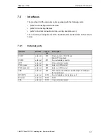
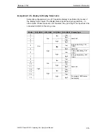
Assignment of the internal ports on the motherboard
Interface
Posi-
tion
Connec-
tor
Description
Memory
X3, X4,
X5
3 SO-DIMM sockets, 64 bit
Processor
X1
Socket for FCPGA processor
Bus expansion
X20
Socket for bus expansion, assigned with ISA and
PCI bus signals)
Power supply
X50
20-pin cable connector for power supply
Floppy
X26
Two drives are possible (82078 compatible)
360 kB, 720 kB, 1.2 MB, 1.44 MB
3F0h – 3F7h, 370h – 377h, can be disabled
IRQ 6, edge-triggered
34-pin, socket for standard floppy drive
3.5” hard disk
inter-
X7
170h-177h, 1F0h-1F7h, can be disabled
IRQ 14, IRQ 15, edge-triggered
40-pin, 2.54 mm plug connector (3.5” HD, primary);
a maximum of 2 drives is possible
CD-ROM drive
nal
X10
170h-177h, 1F0h-1F7h, can be disabled
IRQ 14, IRQ 15, edge-triggered
44-pin, 2 mm plug connector (CDROM, secondary
master);
a maximum of one drive is possible
V.24/TTY module
X28, X29
Connection for V.24/TTY hybrid (physical interface)
Power supply
connection for
CPU fan
X41
Power supply for CPU fan,
3-pin, plug connector
Power supply
connection for
device fan
X42
Power supply for device fan,
3-pin, plug connector
Backup battery
X49
Connection for backup battery,
2-pin, plug connector
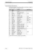
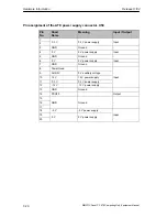
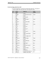
Port to bus module (X20)
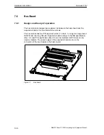
The computer unit has a bus module with a PCI expansion slot and a shared
ISA/PCI slot. Expansion boards can be installed complying with ISA specification
(Rev. 3.1) and PCI specification (Rev. 2.0) with a maximum length of 265 mm
(175 mm for shared ISA/PCI modules) (see Chapter 4). All PCI slots can be used
as masters. Only 5 V PCI modules can be operated.
The power supply of the expansion boards runs via the connection of the bus
module to the basic board. The -5 V voltage is not provided by the power supply
and is generated from the -12 V on the bus module using in-phase control.
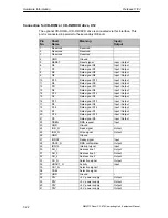
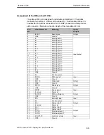
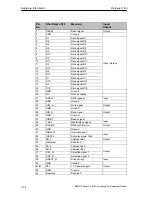
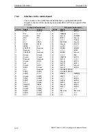
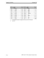
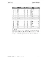
The connection to the basic board is established by a gold-plated ’EISA’ type
two-part connector. All the necessary bus signals (ISA and PCI) are applied to this
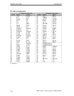
connector. The following table shows the connector pin assignment.
Содержание Simatic PC Panel PC 870
Страница 4: ...Chapter For your notes ...
Страница 12: ...Contents Release 11 02 xii SIMATIC Panel PC 870 Computing Unit Equipment Manual ...
Страница 94: ...Fault Diagnosis Release 11 02 6 10 SIMATIC Panel PC 870 Computing Unit Equipment Manual ...
Страница 130: ...Hardware Information Release 11 02 7 36 SIMATIC Panel PC 870 Computing Unit Equipment Manual ...
Страница 154: ...Index Release 11 02 Index 4 SIMATIC Panel PC 870 Computing Unit Equipment Manual ...


