Connecting and Switching on the Computing Unit
Release 04/02
3-5
Panel PC 670 Computing Unit, Equipment Manual
3.2
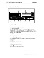
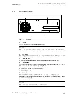
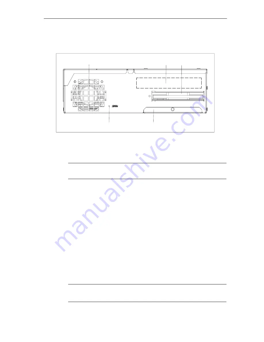
View of Drive Side
1
2
4
3
5
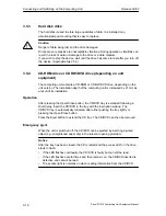
Figure 3-2
Drive side
1
Unit fan
The air vents for the unit fan are located here.
Caution
The air vents must never be covered up, otherwise there is a risk of overheating.
2
Rating plate
The rating plate contains the order no. and production serial no. (F-No.) of the unit.
3
Floppy disk drive
A standard floppy disk drive (1.44 MB) is installed in the computing unit.
4
Front interfaces
The front interfaces are located behind the cover plate below the floppy disk drive.
They serve for the connection of operating fronts:
S
I/O port for connecting front components
S
LVDS display port
5
Reset button
The reset button can be operated with the aid of a pointed object (e.g. a
straightened paper clip). Pressing the Reset key triggers a hardware reset. The PC
is restarted (cold start).
Caution
There may be a loss of data with a hardware reset.
Содержание SIMATIC PC 670
Страница 4: ...For your notes ...
Страница 12: ...Contents Release 04 02 xii Panel PC 670 Computing Unit Equipment Manual ...
Страница 34: ...Starting Up the Computing Unit Release 04 02 2 10 Panel PC 670 Computing Unit Equipment Manual ...
Страница 60: ...Connecting and Switching on the Computing Unit Release 04 02 3 26 Panel PC 670 Computing Unit Equipment Manual ...
Страница 88: ...Maintaining and Extending the Computing Unit Release 04 02 4 28 Panel PC 670 Computing Unit Equipment Manual ...
Страница 132: ...Fault Diagnosis Release 04 02 6 12 Panel PC 670 Computing Unit Equipment Manual ...
Страница 176: ...Distributed configuration Release 04 02 8 6 Panel PC 670 Computing Unit Equipment Manual ...
Страница 194: ...Glossary Release 04 02 Glossary 6 Panel PC 670 Computing Unit Equipment Manual ...
Страница 200: ...Index Release 04 02 Index 6 Panel PC 670 Computing Unit Equipment Manual ...

