background image

Technical specifications 


8.3 Current/power requirements and power supply 


148


Operating Instructions, 01/2021, A5E43920357-AA 
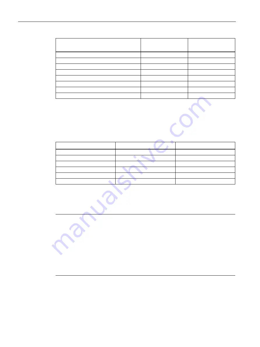
Component 

Current consumption 

(AC-SV, U=230 V) 

Power consumption 

3 × hard disk drives SATA 

0.1 A 

22.0 W 

1 × hard disk drive SATA type Enterprise 

0.05 A 

12.1 W 

2 × hard disk drives SATA type Enterprise 

0.11 A 

24.2 W 

3 × hard disk drives SATA type Enterprise 

0.16 A 

36.3 W 

1 × SSD 2.5" drive SATA 

0.02 A 

3.6 W 

1 x M.2 NVMe SSD 

0.03 A 

5.9 W 

Optional graphics card P440 

0.14 A 

32.8 W  

Optional graphics card P2200 

0.36 A 

83.0 W 

8.3.2


Technical specifications of single power supply (AC) 

Output voltage and maximum current 


Voltage 

Maximum current 

Voltage stability 

+12 V 

10 A 

± 5% 

+12 V 

13 A 

± 5% 

–12 V 

0.3 A 

± 10% 

+5 V 

25 A 

1


± 5% 

+3.3 V 

20 A 

1


± 5% 

+5 V

aux


2.5 A 

+5%, -3% 


1


The total output of the +5 V and +3.3 V voltage must be 

 190 W. 

The inrush current is 

 80 A for 3.6 ms. 


Note 
Information on the dimensioning of fuses in higher-level system circuits 

A fuse that is designed for a typical tripping current of 6.3 A is integrated in the power supply 

unit of the IPC. The pulse currents during startup are also taken into account by the "time lag" 

type. In the case of a fault, this fuse ensures the correct disconnection of the device from the 

power supply system.  
It is recommended that a fuse of at least 6.3 A, plus the power demand of the other devices 

that are also supplied via this circuit, be used for protection of the higher-level power supply 

circuit. The tripping characteristic of the higher-level protection must take into account the 

starting currents of both the IPC and the other devices. 


Содержание SIMATIC IPC547J

Страница 1: ...ning the device 4 Operating the device 5 Expanding and assigning parameters to the device 6 Device maintenance and repair 7 Technical specifications 8 Dimension drawings 9 Standards and approvals 10 Hardware description A Technical support B Markings and symbols C SIMATIC Industrial PC SIMATIC IPC547J Operating Instructions ...

Страница 2: ...by personnel qualified for the specific task in accordance with the relevant documentation in particular its warning notices and safety instructions Qualified personnel are those who based on their training and experience are capable of identifying risks and avoiding potential hazards when working with these products systems Proper use of Siemens products Note the following WARNING Siemens product...

Страница 3: ...History Currently released versions of these operating instructions Version Comments 01 2021 First edition Security information Siemens provides products and solutions with industrial security functions that support the secure operation of plants systems machines and networks In order to protect plants systems machines and networks against cyber threats it is necessary to implement and continuousl...

Страница 4: ...updates subscribe to the Siemens Industrial Security RSS Feed under http www siemens com industrialsecurity Disclaimer for third party software updates This product includes third party software Siemens AG only provides a warranty for updates patches of the third party software if these have been distributed as part of a Siemens software update service contract or officially released by Siemens AG...

Страница 5: ...erface 32 1 4 8 3 Status display of redundant power supply 33 1 4 8 4 Status displays on removable tray for drives 33 1 5 Internal construction of the device 34 1 6 Accessories and spare parts 35 1 6 1 Hardware accessories 35 1 6 2 Software accessories 38 2 Safety instructions 39 2 1 General safety instructions 39 2 2 Safety instructions on transport and storage 42 2 3 Safety instructions for asse...

Страница 6: ...ing the device 75 5 1 Opening the front door 75 5 2 Multi monitoring 75 5 3 Drive configurations 76 5 3 1 RAID systems 76 5 3 1 1 RAID1 system 76 5 3 1 2 RAID5 system 76 5 3 1 3 Hot spare drive in RAID1 or RAID5 systems 77 5 3 2 System with 2 drives 77 5 4 Onboard RAID system 77 5 4 1 Display of a defective drive of an onboard RAID system 77 5 4 2 Onboard RAID1 system Installation options for driv...

Страница 7: ... internal interface 101 6 5 Installing and removing an optional graphics card 103 6 5 1 Installing the optional graphics card 103 6 5 2 Removing the optional graphics card 104 6 6 Installing and removing drives 105 6 6 1 Installing drives in drive cage type A 105 6 6 1 1 Installation conditions for drives in drive cage type A 105 6 6 1 2 Change 2 5 and 3 5 drive in removable tray 107 6 6 1 3 Insta...

Страница 8: ...fications 145 8 1 Applicability of technical specifications 145 8 2 General technical specifications 145 8 3 Current power requirements and power supply 147 8 3 1 Current and power requirements of the system components 147 8 3 2 Technical specifications of single power supply AC 148 8 3 3 Technical specifications of redundant power supply AC 149 8 4 Electromagnetic compatibility 149 8 5 Climatic a...

Страница 9: ...1 A 2 Expansion cards 173 A 2 1 Interrupt assignment of the slots for expansion cards 173 A 2 2 Exclusive PCI hardware interrupt 174 A 3 System resources 175 A 3 1 Currently allocated system resources 175 A 3 2 I O address allocation 175 A 3 3 Interrupt assignments 179 A 3 4 Memory address assignments 181 A 4 Assignment of expansion interfaces to the software in the TIA Portal CP assignment 184 B ...

Страница 10: ...Table of contents 10 Operating Instructions 01 2021 A5E43920357 AA ...

Страница 11: ... Information System ASIS Operating Instructions of the device Installation of the device Steps for connecting the device to the power supply Connecting I O devices Switching the device on Supplied in printed form with the device Supplied data storage medium User manual UM for the motherboard Information on Firmware description Description of the motherboard Description of the interfaces on the mot...

Страница 12: ...ens com cs ww en view 109749690 SIMATIC IPC DiagMonitor Monitoring functions such as with SIMATIC IPC DiagBase with additional extended functions Online at SIMATIC IPC DiagMonitor https support industry siemens com cs ww en view 39129913 SIMATIC IPC Image Partition Creator Information on Backup and recovery of files directories drive partitions Online at SIMATIC IPC Image Partition Creator https s...

Страница 13: ... use in industrial environments Independent product design with a user friendly enclosure concept and front design Rugged all metal enclosure coated over its entire surface blue chromated and or enameled on the outside to protect against corrosion and dirt High EM compatibility for use in industrial business and commercial areas Maximum processor performance in full configuration without loss of p...

Страница 14: ...ap optionally with additional hot spare hard disk Hot Swap in RAID configurations Replacing the drive HDD during operation Hot spare in RAID configurations Rebuild process starts automatically on the reserve drive hot spare drive HDD 3 5 HDD HDD Enterprise or 2 5 SSD as RAID configurations Rapid identification and replacement of the drive in the event of a fault thanks to alarm displays for RAID c...

Страница 15: ...PC tower kit optional Universal use as industrial workstation or industrial server Pre installed and activated operating systems Windows 10 Enterprise 2019 LTSC 64 bit Windows Server 2019 64 bit incl 5 clients Fast restoration of the delivery state by restoring from USB stick 1 3 Scope of application The SIMATIC IPC offers system integrators cabinet designers system engineers and machine designers...

Страница 16: ...esign of the device 1 4 1 Front panel Front Front door is closed 19 mounting bracket with handle Fan cover of front fan with openings for ventilation of the device locked by front door System status displays Page 31 Front door lockable protection against unauthorized access Lock Key vertical open Key horizontal closed ...

Страница 17: ...of the enclosure cover On off button see Operator controls Page 28 Rese pushbutton see Operator controls Page 28 Drive cage in this case type A depending on the expansion variant see Drive cage type A Page 18 Drive cage type B Page 20 Type C drive holder Page 21 Interfaces on the front of the device see Device ports Page 24 Front fan support ...

Страница 18: ... the outside without opening the device The removable trays can be locked thus protecting the drives from unauthorized access 0 Mounting location 0 for 2 5 drive in removable tray 3 5 drive in removable tray 1 Mounting location 1 for 2 5 drive in removable tray 3 5 drive in removable tray 2 Mounting location 2 for 2 5 drive in removable tray 3 5 drive in removable tray 3 Mounting location 3 5 25 t...

Страница 19: ...g Instructions 01 2021 A5E43920357 AA 19 Components of the removable tray 1 Status display Page 33 2 Status display Page 33 3 Number of the mounting location here Mounting location 0 4 Lock See also Installation conditions for drives in drive cage type A Page 105 ...

Страница 20: ...erefore not accessible The drives are particularly well protected against vibration and oscillation vibration dampened drive cage 0 Mounting location 0 5 25 tray for 2 5 drive in the assembly kit 3 5 drive in the assembly kit 5 25 drive or 5 25 component 1 Mounting location 1 5 25 tray for 2 5 drive in the assembly kit 3 5 drive in the assembly kit 5 25 drive or 5 25 component 2 Mounting location ...

Страница 21: ...e and is located behind the front door The drive cage type C consists of a design cover and a drive bay plate The drive bay plate is accessible after the design cover has been removed You can mount 2 5 and 3 5 drives HDD or SSD on the drive bay plate Design cover mounted on the drive bay plate 2 5 drive on the drive bay plate 3 5 drive on drive bay plate Six screws for attaching or loosening the d...

Страница 22: ...1 A5E43920357 AA Numbering of mounting locations 0 Mounting location 0 1 Mounting location 1 See also Installation conditions for drives in the drive cage type C Page 125 Safety instructions on device and system extensions Page 48 Open the device Page 93 Switching off the device Page 72 ...

Страница 23: ...otential bonding line Page 59 COM2 optional Holes for attaching the retainer for the internal USB stick Opening prepared for Kensington lock Slot brackets or connections of inserted expansion cards Connections of the optional graphics card here optional P440 graphics card Page 24 Fixing screws for strain relief Page 68 Device ports Page 24 Power supply Page 28 here Single power supply ...

Страница 24: ...ront of the device behind the front panel Note the technical specifications of the interfaces Page 158 No Connection socket USB 3 1 Gen 1 Type A X66 SuperSpeed backwards compatible to USB 3 0 2 0 1 1 each 900 mA high current1 USB 3 1 Gen 1 Type A X67 SuperSpeed backwards compatible to USB 3 0 2 0 1 1 each 900 mA high current1 1 Sum of the currents on the USB interfaces of the device including the ...

Страница 25: ...OUT X91 Microphone IN X92 2 x USB 2 0 Type A backwards compatible to USB 1 1 each 500 mA high current1 X64 X65 2 x USB 3 1 Gen 1 Type A SuperSpeed backwards compatible to USB 3 0 2 0 1 1 each 900 mA high current1 X62 X63 2 x USB 2 0 Type A backwards compatible to USB 1 1 each 500 mA high current1 X60 X61 DisplayPort labeling on the device DPP for connecting monitors to internal graphics card DPP1 ...

Страница 26: ...sonville i219 LM AMT capable iAMT and teaming cannot be used simultaneously on the LAN interface The following teaming modes are supported Adapter Fault Tolerance AFT Adaptive Load Balancing ALB IEEE 802 3ad Dynamic Link Aggregation DLA Static Link Aggregation SLA Switch Fault Tolerance SFT Audio Line IN X90 Headphone OUT X91 Microphone IN X92 2 x USB 3 1 Gen 2 Type A SuperSpeed backwards compatib...

Страница 27: ...luding the internal USB interfaces 3 A 2 Maximum cable length max3 m depending on the attenuation of the cable and the maximum data rate of the connection Use the original connection technology of the I O devices to be connected without adapters and without extensions Connections of the optional graphics cards The optional graphics card is an expansion card After installing this expansion card the...

Страница 28: ... for power plugs with single and redundant power supply Single power supply Redundant power supply 1 4 7 Operator controls WARNING Risk of electric shock The buttons and switches described in the following do not fully disconnect the device from the line voltage You also need to the notes and information under Switching off the device Page 72 ...

Страница 29: ... supply On Off switch On off switch and reset button The on off button and the reset button are located on the front of the device behind the front door On off button Reset button The On off button starts and shuts down the operating system For information on switching the device on and off see Switching on the device Page 71 and Switching off the device Page 72 The reset button is for the emergen...

Страница 30: ...ns 01 2021 A5E43920357 AA Alarm reset button redundant power supply The alarm reset button is only available for devices with redundant power supply Use the alarm reset button to switch off the signal tone of the redundant power supply in the event of an error Alarm reset button ...

Страница 31: ...atus POWER Operating mode of the PC OFF Switched off or disconnected from the mains YELLOW Hibernate or Shut down energy saving mode Flashing YELLOW Standby energy saving mode GREEN PC in operation HDD Access to hard disk OFF No access GREEN Access ETHERNET 1 ETHERNET 2 ETHERNET 3 Ethernet status display OFF No connection No data traffic GREEN Data traffic WATCHDOG Watchdog status OFF Not activate...

Страница 32: ... RAID synchronization running RAID is not OK The hard disk newly integrated in case of error is synchronized with an existing hard disk All RED LEDs are lit up RAID is not OK The faulty drive could not be localized by the monitoring software It may be possible to detect the defective drive with the RAID software Information is available at RAID1 system Page 76 RAID5 system Page 76 or Hot spare dri...

Страница 33: ... The module is in operation and functioning Redundancy is in effect when both modules are operating RED Module failed no redundancy in effect 1 4 8 4 Status displays on removable tray for drives No Status display Meaning Status Meaning of the status Power Status of the removable tray OFF Device switched off Power supply not connected No drive installed GREEN Device is switched on and a drive is in...

Страница 34: ...ply single or redundant here in the example Single power supply Heat sink of the processor Rod with card holders for expansion cards Slots for memory modules Drive cage here in the example Drive cage type A or type B Guide rail for long expansion cards Motherboard Expansion card slots Slot brackets numbering of the slots for expansion cards on the enclosure ...

Страница 35: ...e The retainer is a mechanical safety device for the internal USB interface It optimizes the protection of an internal USB memory stick against loads caused by vibration and shock during transportation or operation This increases the reliability and operational safety of the device 6ES7648 1AA00 0XK0 Tower Kit for SIMATIC IPCs You can use the Tower Kit to convert the device into an industrial Towe...

Страница 36: ...0 Connection of dual head adapter to the optional graphics card possible with the following adapters mDP to VGA adapter Mini DisplayPort to VGA 6ES7648 3AL00 0XA0 mDP to DVI D adapter Mini DisplayPort to DVI D available as single pack or 3 pack 1 adapter 6ES7648 3AK00 0XA0 3 adapters 6ES7648 3AK00 1XA0 mDP DP adapter Mini DisplayPort to DisplayPort available as single pack or 3 pack 1 adapter 6ES7...

Страница 37: ... to open the device or remove it from the control cabinet The result is the following advantages for service and maintenance data backup and data transfer Replacement of a failed hard disk during operation hot swap Downloading different system states or operating systems from different hard drives during a short period of time Simplified data backup by copying for example to a backup hard drive Si...

Страница 38: ...age Partition Creator SIMATIC IPC Image Partition Creator enables easy backup and quick recovery of individual data and files complete hard disks and other data storage media The intuitive user interface provides disk and partition management functions SIMATIC IPC DiagMonitor In addition to the local monitoring options SIMATIC IPC DiagMonitor offers options for remote monitoring of IPCs communicat...

Страница 39: ...ted incorrectly into a system Death or serious bodily injury can result Make sure that only appropriately qualified personnel work on the device or on a system Danger to life when the control cabinet is open WARNING Electrocution risk when control cabinet is open When you open the control cabinet there may be a dangerous voltage at certain areas or components Touching these areas or components can...

Страница 40: ...s easily accessible Risk due to strong high frequency radiation NOTICE Observe immunity to RF radiation The device has increased immunity to high frequency radiation in accordance with the information on electromagnetic compatibility Page 149 Radiation exposure exceeding the specified immunity limits can impair device functions result in malfunctions and therefore injuries or damages Note the info...

Страница 41: ...verheating When setting up and installing the device observe the important information in section Safety instructions on ambient and environmental conditions Page 45 Danger when changing the battery When changing the battery note the important information in the section Changing the backup battery Page 135 Avoiding functional restrictions NOTICE Possible functional restrictions in case of non vali...

Страница 42: ...pressure and moisture may impact the unprotected unit Damaged packaging indicates that ambient conditions have already had a massive impact on the device and it may be damaged This may cause the device machine or plant to malfunction Keep the original packaging Pack the device in the original packaging for transportation and storage Danger due to damage to the device WARNING Electric shock and fir...

Страница 43: ... or until the device is completely dry before switching it on 2 3 Safety instructions for assembly Fire protection enclosure Note The device meets the requirements for fire protection enclosures in accordance with IEC EN UL 61010 2 201 It can therefore be installed without an additional fire protection cover Approvals expire if the instructions are not observed WARNING Approvals expire if the inst...

Страница 44: ...ment in the rack should be such that a hazardous condition is not caused due to an uneven mechanical load see notes under Climatic and mechanical and ambient conditions Page 150 Circuit overload When connecting the device observe the information on the power supply on the information label on the rear of the device Reliable grounding Ensure that the equipment installed in the rack is safely ground...

Страница 45: ... system the approvals according to IEC EN UL CSA 61010 2 201 will become void There is a risk of overheating and personal injury Danger if ambient conditions are unsuitable NOTICE Ambient conditions and chemical resistance Unsuitable ambient conditions may cause faults or damage the device In the event of non compliance the warranty and approval expire according to IEC EN UL CSA 61010 2 201 When t...

Страница 46: ...e supply of clean air Ensure adequate ventilation of the device Do not obstruct the venting slots of the device Always maintain a minimum clearance of 50 mm to the area of the ventilation slots The device meets the requirements for fire protection enclosures in accordance with IEC EN UL CSA 61010 2 201 You can therefore install it without an additional fire protection enclosure The connected or bu...

Страница 47: ... hotplug capable may only be connected after the device has been disconnected from the power supply Danger due to regenerative feedback NOTICE Damage through regenerative feedback A connected or installed component can cause voltage to be fed back to ground in the device This can damage the device Do not supply voltage into the device through connected or installed I O devices such as a USB drive ...

Страница 48: ...y instructions on device and system extensions Contact your technical support team or the point of sale to find out which device and system expansions are suitable for installation Risk due to device and system expansions NOTICE Damage caused by device and system extensions Device and system expansions may contain faults and affect the entire device machine or plant Device and system expansions ma...

Страница 49: ...y accessible Risk when opening the device WARNING Risk of malfunctions and electric shock Improper intervention in the device endangers operational reliability and may damage the device The results are personal injuries and damage to the plant Take the following precautions Disconnect the power plug before you open the device Close the device after every intervention NOTICE Electrostatic sensitive...

Страница 50: ... of the device Expansion cards generate additional heat The device can overheat or cause a fire Observe the safety and installation instructions for the expansion cards Note the maximum power consumption permitted for the device see General technical specifications Page 145 Limitation of liability Note All technical specifications and approvals of the device only apply if you use expansion compone...

Страница 51: ...ered Keys for front door 2 keys For device with drive cage type A 2 keys for removable trays Self adhesive enclosure feet 4 units if ordered with power supply cable Supplied data storage medium On the supplied data storage medium read only you will find Software and tools to recover your ordered Microsoft Windows operating system Device drivers for installation in operating systems Quick Install G...

Страница 52: ...ents Quick Install Guide SIMATIC IPC547J with link and QR code to the online form for quality control quality control notification in the SIEMENS After Sales Information System ASIS Product Information Important notes on your device 3 1 2 Checking the delivery package WARNING Electric shock and fire hazard due to damaged device Devices damaged by incorrect storage or transport can cause personal i...

Страница 53: ...pairs Complete the online form for quality control quality control notification 5 Please keep the documentation in a safe place It is required for initial commissioning and is part of the device 6 Note down the Device identification data Page 53 3 1 3 Device identification data The device can be clearly identified with the help of this identification data in case of repairs or loss The following i...

Страница 54: ...1 Mounting types Note If the device is permanently installed mounted on telescopic rails or set up as a tower it must not be subjected to vibration loads during operation In these cases use only SSDs and not HDDs as drives Horizontal Mounting with cabinet brackets The device can be installed horizontally in control cabinets and 19 rack systems This installation type meets the requirements in accor...

Страница 55: ...ce on a horizontal base made of metal and secure it against falling The following are available from Rittal device bases https www rittal com de de product list action categoryPath PG0001 for this purpose Rittal Type TE 7000 620 Rittal Type VR 5501 655 Rittal Type DK 5501 655 You should also observe the information of the manufacturer of the device bases Vertical with tower kit For the vertical op...

Страница 56: ...trol cabinet is open When you open the control cabinet there may be a dangerous voltage at certain areas or components Touching these areas or components can cause death or serious bodily injury Always disconnect the cabinet from the mains before opening it Ensure that the power to the control cabinet cannot be turned on accidentally CAUTION Risk of physical injury The device is too heavy to be mo...

Страница 57: ...7 AA 57 Bore holes for telescopic rails Holes for standard enclosure Holes for short enclosure The dimensions for the holes can be found under Dimension drawing of the telescope rails Page 165 Detailed information on the drives can be found under Technical specifications of the telescopic rails Page 159 ...

Страница 58: ...materials are rated for the maximum current input and ambient temperature of the device and meet the requirements of the following standards ANSI UL 498 and CSA C22 2 No 42 CSA C22 2 No 182 1 CSA C22 2 No 182 2 CSA C22 2 No 182 3 Country specific information on supply voltage for outside of USA and Canada Supply voltage 230 V AC This device is supplied with a safety tested power cord and may only ...

Страница 59: ...a minimum cross section of 2 5 mm2 Procedure 1 Make the connection for functional ground via an equipotential bonding line to the equipotential bonding rail or grounding bar of the control cabinet in which the device is installed 3 3 3 Connecting the power supply 3 3 3 1 Connect single power supply AC WARNING Injury to persons or damage to property when operated on an incorrect power supply system...

Страница 60: ...ible AC circuit breaker near the device Requirement You have observed the information under Country specific information on supply voltage Page 58 Procedure 1 Make sure that the on off switch is in the 0 off position Information on the position of the on off switch is available in Operator controls Page 28 2 Connect the power plug to the corresponding socket Information on the position of the sock...

Страница 61: ...permitted WARNING Risk of electric shock The on off button and on off switch do not fully disconnect the device from the mains There is also a risk of fire if the device or connecting lines are damaged Always fully disconnect the device from the mains voltage before performing work on the device or when the device will not be used over an extended period of time For control cabinet mounting Use a ...

Страница 62: ...of the power supply modules works a warning signal sounds You turn off the warning signal by pressing the alarm reset button on the working power supply module You can find information on the position of the alarm reset button under Operator controls Page 28 5 To prevent unintentional disconnection of the power plug secure the power plug on the device 6 Remove the two retaining screws 7 Screw on t...

Страница 63: ...ed without adapters or extensions 1 Connect the I O devices to the respective interfaces Information on the position of the interfaces is available in Device ports Page 24 2 Secure the cables Page 68 with a strain relief 3 3 4 2 Connecting audio devices Requirement You have observed the information under Connecting external devices Page 63 and under Technical specifications of the interfaces Page ...

Страница 64: ... 3 x mDP You can use adapters to connect monitors to other graphics ports at the connection sockets of the optional P400 graphics card You can find information on the connection sockets on the rear of the device under Device ports Page 24 You can find information on the adapters under Hardware accessories Page 35 Connection socket on monitor Connection socket on the internal graphics card Connecti...

Страница 65: ...to other graphics ports at the connection sockets of the optional P400 graphics card You can find information on the connection sockets on the rear of the device under Device ports Page 24 You can find information on the adapters under Hardware accessories Page 35 Connection socket on monitor Connection socket on the internal graphics card Connection socket on the optional P400 graphics card DP DP...

Страница 66: ...onnect monitors to other graphics ports at the connection sockets of the optional P2200 graphics card You can find information on the connection sockets on the rear of the device under Device ports Page 24 You can find information on the adapters under Hardware accessories Page 35 Connection socket on monitor Connection socket on the internal graphics card Connection socket on the optional P2200 g...

Страница 67: ...ccessories 2 Labeling on the device Requirement You have observed the information in the following sections Connecting external devices Page 63 Procedure 1 Connect the monitors to the rear of the device Page 24 For information on connecting monitors with adapters see Hardware accessories Page 35 2 On delivery the device is set for multi monitoring If the delivery state settings have been changed c...

Страница 68: ...rated via Standard Ethernet interfaces RT SIMATIC NET Use this software package to create operate and configure an innovative network for Field Control level Additional information is available under SIMATIC NET http w3 siemens com mcms automation en industrial communications Pages Default aspx The software package and the documentation are not included in the scope of delivery Additional informat...

Страница 69: ...on of the sockets is available in Device ports Page 24 2 Screw the desired strain relief with the fixing screw on the left and or right of the device 3 Insert the detachable cable ties in the respective openings of the strain relief and fasten the cables with the cable ties 4 Fasten the cables to the corresponding openings in the strain relief using simple cable ties Example Cable fastened to stra...

Страница 70: ...Installing and connecting the device 3 3 Connecting the device 70 Operating Instructions 01 2021 A5E43920357 AA ...

Страница 71: ...mmissioning the installed Windows operating system in the documentation on the supplied data storage medium See also Important instructions and manuals for operating the device Page 11 4 2 Configuring automatic switch on of device In the firmware settings you can specify that the device starts up again automatically after being disconnected from the supply voltage for up to two minutes as soon as ...

Страница 72: ...e Fully disconnecting the device from the line voltage WARNING Risk of electric shock from mains voltage The on off button and on off switch do not fully disconnect the device from the mains There is also a risk of fire if the device or connecting lines are damaged Always fully disconnect the device from the mains voltage before performing work on the device or when the device will not be used ove...

Страница 73: ... switched off and restarted Data in the main memory is deleted Data on the data storage media may be lost The device may be damaged Perform a hardware reset only in the case of an emergency Hardware reset with on off button Press the on off button for more than 4 seconds The unit switches off To switch the device on again press the on off button again Hardware reset with reset button Press the res...

Страница 74: ...Commissioning the device 4 3 Switching off the device 74 Operating Instructions 01 2021 A5E43920357 AA ...

Страница 75: ...Multi monitoring In its delivery state the device is equipped with a graphics card To connect several monitors to the device at the same time Page 64 multi monitoring you can install an additional so called optional graphics card Page 103 Note Information on graphics cards which support multi monitoring can be obtained from your local representative see Service and support Page 185 ...

Страница 76: ...tor the RAID1 system Onboard RAID system Page 78 Intel Rapid Storage Technology See also Install drives on the drive bay plate Page 125 Drive cage type A Page 18 5 3 1 2 RAID5 system A RAID5 system works according to the stripping with parity principle In the event of a defective drive or cable problems the RAID5 system can continue to work on the remaining drives and thus achieves a high level of...

Страница 77: ... 3 2 System with 2 drives You can order the device as a system with two drives For information on hard disk capacity refer to your order documentation When the device ships the second drive is then connected to SATA port 1 and not yet set up You have the option of backing up your data to this drive You can find information on how to boot the device from the second drive in the detailed firmware BI...

Страница 78: ...rd RAID system the onboard RAID system is pre configured by default If you subsequently set up an onboard RAID system you still have to configure it Requirement The drives required for the onboard RAID system are installed in the device see Onboard RAID1 system Installation options for drives Page 78 Onboard RAID5 system Installation options for drives Page 78 Setting up the onboard RAID system in...

Страница 79: ...e list You can find the assignment of the drive to the mounting location in the drive bay in front of the drive model designation see 8 Select Create Volume In the next window the details of the RAID system RAID volume that you have just set up are displayed The onboard RAID system is set up 9 To exit the firmware settings press the F4 button Save Exit and confirm the subsequent dialog with Y Sett...

Страница 80: ... report on the onboard RAID system 1 Select the Help tab 2 Select System Report Save 5 4 4 3 Integrating a new drive into an onboard RAID system The onboard RAID system is configured in the delivery state so that a new drive must be integrated manually when a defective drive was replaced You can also configure the onboard RAID system in such a way that the new drive is automatically mounted when t...

Страница 81: ... replaced You can configure the manual integration of the drive or check the settings yourself 1 Select Start Intel Intel Rapid Storage Technology 2 Select the Preferences menu 3 Go to the Automatic Rebuild area and deactivate the Auto rebuild on hot plug option Manual integration of the replaced drive in the event of an error You can manually integrate a replaced drive in the onboard RAID system ...

Страница 82: ...Mark as Spare window with Yes 5 4 5 Data synchronization in the RAID system NOTICE Danger of incorrect operations on machine and plant delayed system reaction during data synchronization Data is synchronized if a drive fails The system can respond with a delay depending on the size of the drive and system load In extreme cases the execution of keyboard mouse or touch screen commands may be briefly...

Страница 83: ...an is monitored at the following positions Front panel Processor Optional graphics card Power supply not redundant Drive cage type A Status display FAN Page 31 Fan alarm is output Watchdog Monitoring of the system status and message as to whether a station is still operational If the watchdog is not operated within a configured monitoring time a watchdog alarm is output A change to the monitoring ...

Страница 84: ...perating system the SIMATIC IPC DiagBase monitoring software is installed Information on the software and documentation of SIMATIC IPC DiagBase can be found under Important instructions and manuals for operating the device Page 11 5 5 3 SIMATIC IPC DiagMonitor The SIMATIC IPC DiagMonitor monitoring software can be ordered optionally If a device is ordered with SIMATIC IPC DiagMonitor the software ...

Страница 85: ...eration keyboard video mouse redirection With KVM Redirection you can control SIMATIC IPCs remotely even if they have no operating system or a defective operating system A KVM remote session is always possible with the KVM server integrated in the firmware This allows you to restart the IPC and change firmware BIOS settings remotely Remote power management SIMATIC IPCs can be turned on and off and...

Страница 86: ...nstructions and manuals for operating the device Page 11 5 6 2 2 Activate Intel AMT 1 Switch on the device or restart it 2 Immediately after turning on the device as soon as the message Press DEL or ESC to enter setup appears press and hold the Del or Esc button The firmware user interface opens Here you have the following keys available for navigation Action Key Select entry then confirm selectio...

Страница 87: ... 2 Log in to MEBx and assign a password Page 87 3 Configure the Intel AMT functions in the Options of the MEBx Page 88 Logging onto MEBx assigning password 1 Select the Intel R Management Engine BIOS Extension option on the Main Page with the arrow keys 2 Select the MEBx Login option 3 Confirm your selection with the Return key 4 Enter the following Intel R ME Password when logging on the first ti...

Страница 88: ... motherboard Note The MEBx setting options depend on whether or not your device supports Intel AMT Intel R ME General Settings MEBx setting Meaning Change ME Passwort Here you can change the current password for logging onto MEBx FW Update Firmware updates of the Intel Management Engine ME can be installed not installed or only installed after entering the password Intel R AMT MEBx setting Meaning...

Страница 89: ...ity Feature Selection Enabled The following network settings can be configured Intel R ME Network Name Settings Host Name Domain Name Shared Dedicated FQDN Dynamic DNS Update TCP IP Settings Wired LAN IPV4 Configuration DHCP mode Activate Network Access only if Manageability Feature Selection Enabled Enables the network interface This MEBx setting is only available when the network is not enabled ...

Страница 90: ...ace opens Here you have the following keys available for navigation Action Key Select entry then confirm selection Arrow keys on the keyboard Confirm selection Enter key Back to previous window Esc key 3 Select Advanced AMT Configuration 4 Assign the Enabled value to the firmware setting Unconfigure ME 5 Press the button F4 Save Exit and confirm the subsequent dialogue with Y 6 Switch off the devi...

Страница 91: ... Procedure 1 Switch on the device or restart it 2 Immediately after turning on the device as soon as the message Press DEL or ESC to enter setup appears press and hold the Del or Esc button The firmware user interface opens Here you have the following keys available for navigation Action Key Select entry then confirm selection Arrow keys on the keyboard Confirm selection Enter key Back to previous...

Страница 92: ...s provides an improved protection from manipulation of the device NOTICE Import restrictions for the Trusted Platform Module Use of the Trusted Platform Module is subject to legal restrictions in some countries and is not permitted there Always observe the respective import restrictions of the country in which the device will be used Activating the Trusted Platform Module You can find information ...

Страница 93: ...ions under Safety instructions on device and system extensions Page 48 T10 screwdriver Procedure 1 Fully disconnect the device from the line voltage see Switching off the device Page 72 2 Unplug all connecting cables 3 Open the front panel Page 75 4 Unscrew the locking screw of the enclosure cover 5 Push the enclosure cover back 6 Lift up and remove the enclosure cover ...

Страница 94: ...cards You can find the permitted dimensions for expansion cards under Dimension drawing of the expansion cards Page 164 To rule out contact problems and malfunctions do not use any expansion cards that exceed the maximum permissible height For expansion cards with a lower mounting height low profile expansion card three long card retainers are enclosed with the device Use these instead of the long...

Страница 95: ...ge 93 3 Hold the bar with the card retainer on both ends and remove it by pulling it upwards The bar is latched on both ends 4 Remove the slot bracket for the required slot 5 Insert the expansion card into the free slot on the motherboard 6 Secure the expansion card with the screw 7 Re insert the bar with the card retainers 8 Detach the card retainer in question and place it on the expansion card ...

Страница 96: ...r Open the device Page 93 3 Hold the bar with the card retainer at both ends and remove it by pulling it upwards The bar is latched on both ends 4 Disconnect all cables and the screw of the expansion card that you wish to remove 5 Remove the expansion card from the slot If you do not wish to install a new expansion card install the corresponding slot bracket with the screw 6 Close the device 6 3 I...

Страница 97: ... permitted Use the modules to expand the memory capacity of your device to a maximum of 128 GB Depending on the number of memory modules used these are plugged into defined slots on the motherboard The slots are labeled on the motherboard Combination option Channel A external Channel B Maximum expansion DIMM_A1 DIMM_A2 DIMM_B1 DIMM_B2 Combination 1 4 GB 8 GB 16 GB 32 GB 32 GB Combination 2 4 GB 8 ...

Страница 98: ... install several memory modules install them one after the other in the following order Memory module 1 DIMM_A1 slot Memory module 2 DIMM_A2 slot Memory module 3 DIMM_B1 slot Memory module 4 DIMM_B2 slot The slots of the memory modules are labeled on the motherboard Procedure 1 Fully disconnect the device from the line voltage see Switching off the device Page 72 2 Open the device Be sure to follo...

Страница 99: ... inserting pay attention to the cutout see figure which must be in line with the coding of the base 6 Insert the memory module in the slot perpendicular to the motherboard 7 To prevent tilting press evenly on both sides of the memory module until both interlocks audibly engage 8 Close the device Display of a changed memory configuration A changed memory allocation is automatically recognized when ...

Страница 100: ...e 2 DIMM_B1 slot Memory module 3 DIMM_A2 slot Memory module 4 DIMM_A1 slot The slots of the memory modules are labeled on the motherboard Procedure 1 Fully disconnect the device from the line voltage see Switching off the device Page 72 2 Open the device Be sure to follow the important instructions under Open the device Page 93 3 To obtain better access to the memory modules remove expansion cards...

Страница 101: ...ries Page 35 Screwdriver TX10 Procedure 1 Fully disconnect the device from the line voltage see Switching off the device Page 72 2 Open the device Be sure to follow the important instructions under Open the device Page 93 3 Insert the USB stick into the socket of the internal USB interface on the motherboard Page 171 4 Screw the two hexagon bolts with two of the enclosed screws into the first and ...

Страница 102: ... assigning parameters to the device 6 4 Connecting a USB stick to the internal interface 102 Operating Instructions 01 2021 A5E43920357 AA 7 Fix the retainer by turning the screw on the guide rail 8 Close the device ...

Страница 103: ...toring You can obtain information on this from your local contact person see Service and support Page 185 You have made a note of the firmware settings because the firmware settings of the device can be deleted when an optional graphics card is installed You can find information on this in the firmware description of the device see Important instructions and manuals for operating the device Page 1...

Страница 104: ...ctor follow these steps 1 Connect a monitor to the DPP port or the DVI D port 2 During the boot phase when a boot message appears press the Del or Esc button 3 Select Chipset System Agent SA Configuration 4 Assign the Auto value to the firmware setting Primary Display 6 5 2 Removing the optional graphics card Requirement You know the important safety instructions under Safety instructions on devic...

Страница 105: ...ovable tray Page 107 2 Drive cage type A Mounting location 0 Mounting location 1 2 5 drive or 3 5 drive in removable tray Page 107 3 Drive cage type A Mounting location 0 Mounting location 1 Mounting location 2 2 5 drive or 3 5 drive in removable tray Page 107 4 Drive cage type A Mounting location 0 Mounting location 1 Mounting location 2 2 5 drive or 3 5 drive in removable tray Page 107 Drive cag...

Страница 106: ... drive in removable tray Page 107 Mounting location 3 2 5 drive or 3 5 drive in removable tray with 5 25 mounting frame Page 109 5 25 drive or 5 25 component Page 121 2 x internal in the device 2 x HDD inside on the side panel of the device Page 123 Possible drive configurations in drive cage type A You can implement the following drive configurations in the drive cage type A and on the side panel...

Страница 107: ...tions for drives in drive cage type A Page 105 When replacing an HD T10 screwdriver When replacing an SSD T8 screwdriver The device you wish to replace is inactive NOTICE Risk of damaging the drive and data loss Drives in removable trays can only be exchanged in conjunction with RAID1 and RAID5 during operation hot swap When you remove the drive while data is being written to it you may damage the...

Страница 108: ...ve the drive The left figure shows as drive a 3 5 HDD the right figure a 2 5 SSD 7 Carefully insert the new drive into the removable tray Take care not to touch the contacts of the drive when you do this 8 Fasten the new drive with the screws to the base of the removable tray Only use the original screws 9 Carefully insert the removable tray into the drive cage of the device again 10 Fold the tray...

Страница 109: ...Requirement You know the important safety instructions under Safety instructions on device and system extensions Page 48 The device is equipped with the drive cage type A You know the information under Installation conditions for drives in drive cage type A Page 105 An original replacement part For information on replacement parts refer to Hardware accessories Page 35 T10 screwdriver Procedure 1 F...

Страница 110: ...Press on the surfaces on the two side mounting bars of the 5 25 component Press and hold surface to push the 5 25 component forward out of the drive holder 4 Remove the left and right mounting bars from the cover Note Reinstalling an empty 5 25 component The mounting rails are labeled with L and R and can be re installed on the blanking cover in the same way if necessary The top of the blanking co...

Страница 111: ...he key 12 Close the device 13 Connect the power supply 6 6 1 4 Installing a backplane for removable tray The backplane of the removable tray is installed from inside at the back end of the drive cage type A and is equipped with interfaces for data cables to the motherboard This enables the convenient connection of the data cables from the motherboard to the drive in the removable tray at these int...

Страница 112: ...ow the important instructions under Open the device Page 93 3 Press the locks of the cover together inside the device and keep them pressed 4 Push the locks to the front in the direction of the arrow 5 Remove the cover upwards at an angle at the front of the device 6 On the front of the drive cage remove the cover of the mounting locations which may be located to the right of the cover 7 Remove al...

Страница 113: ... cage All centering openings of the backplane lie in the centering pins The backplane is clipped in behind the latches All backplanes lie exactly underneath each other vertically aligned when viewed from above 9 Reinstall the required blanking plates or removable trays 10 Insert the cover into the front of the device 11 At the backplane connect the data cables with the corresponding interfaces on ...

Страница 114: ...e removable tray at these interfaces Figure 6 1 Removable tray with backplane Requirement You know the important safety instructions under Safety instructions on device and system extensions Page 48 The device is fully disconnected from the line voltage see Switching off the device Page 72 The device is equipped with the drive cage type A Procedure 1 Open the device Be sure to follow the important...

Страница 115: ...1 6 6 2 Installing drives in the drive cage type B 6 6 2 1 Installation conditions for drives in drive cage type B Note If the device is permanently installed mounted on telescopic rails or operated as tower it can only be subjected to the vibration stresses described below during operation The restrictions do not apply to the use of SSD Number of drives per system and their mounting locations You...

Страница 116: ...tion 1 Mounting location 2 2 5 drive or 3 5 drive in the assembly kit Page 118 5 25 drive or 5 25 component Page 121 4 Drive cage type B Mounting location 0 Mounting location 1 Mounting location 2 2 5 drive or 3 5 drive in the assembly kit Page 118 5 25 drive or 5 25 component Page 121 1 x internal in the device 1 x HDD inside on the side panel of the device Page 123 5 Drive cage type B Mounting l...

Страница 117: ...ng vibration loads during operation The restrictions do not apply to the use of SSD Drives in drive cage type B Drives in drive cage type B may be exposed to the following maximum vibration loads during operation 10 58 Hz 0 015 mm 58 Hz to 500 Hz 2 m s2 Vibrations must not exceed 500 Hz Possible drive configurations You can implement the following drive configurations in the drive cage type B and ...

Страница 118: ...tructions on device and system extensions Page 48 The device is equipped with a drive cage type B You know the information under Installation conditions for drives in drive cage type B Page 115 An original spare part that is an HDD SDD assembly kit for 5 25 tray approved for this device For information on replacement parts refer to Hardware accessories Page 35 When replacing a 3 5 HDD T10 screwdri...

Страница 119: ...ainst the surfaces of the drive mounting bars The assembly kit is unlocked 5 Slide the assembly kit on the drive mounting bars forward out of the device and set it aside 6 Remove the left and right drive mounting bars and the drive bay cover from the drive Note The drive cover is labeled L and TOP The drive mounting bars are labeled L and R respectively ...

Страница 120: ... bay Drive cage with 3 5 HDD Drive bay with 2 5 SSD 8 Install the new drive in the drive bay Ensure that the new drive faces upwards 9 Fasten the new drive using four screws Start at the hole marked with 1 on the drive bay 10 Attach the left and right drive mounting bars on the drive bay 11 Slide the drive bay evenly and without tilting 3 4 not completely into the guide rail of the drive cage ...

Страница 121: ...rive cage type B Requirement You know the important safety instructions under Safety instructions on device and system extensions Page 48 The device is equipped with a drive cage type A or type B You know the information under Installation conditions for drives in drive cage type A Page 105 Installation conditions for drives in drive cage type B Page 115 An original spare part that is a 5 25 drive...

Страница 122: ...and hold surface to push the 5 25 component forward out of the drive holder 4 Remove the left and right mounting bars from the cover Note The mounting bars are labeled L and R The top of the blanking cover is also marked 5 Screw the right and left drive mounting bars to the new drive Take care not to touch the contacts of the drive when you do this The blanking plate is no longer required 6 Slide ...

Страница 123: ... is equipped with a drive cage type A or type B A device with standard enclosure You know the information under Installation conditions for drives in drive cage type A Page 105 Installation conditions for drives in drive cage type B Page 115 A drive bay plate with a corresponding drive HDD approved for this device For information on replacement parts refer to Hardware accessories Page 35 T10 screw...

Страница 124: ...A5E43920357 AA 2 Screw from outside the drive bay plate on the inside to the side panel of the enclosure at position or position The SATA connections each lie in the middle 3 Connect the SATA cables to the required SATA connectors of the motherboard and to the drive position 4 Close the device 5 Connect the power supply ...

Страница 125: ...Requirement You know the important safety instructions under Safety instructions on device and system extensions Page 48 The device is equipped with a drive cage type C You know the information under Installation conditions for drives in the drive cage type C Page 125 Original replacement parts that is drives approved for this device see Hardware accessories Page 35 When installing 3 5 HDDs T10 sc...

Страница 126: ...oving drives 126 Operating Instructions 01 2021 A5E43920357 AA 6 Mount one or more drives on the rear of the drive bay plate Note the holes 3 5 HDDs Holes on the front of the drive bay plate and on the HDDs 2 5 SSDs Holes on the front of the drive bay plate and on the SSDs ...

Страница 127: ...e design cover back onto the drive bay plate 8 Reinsert the drive bay plate and screw the drive bay plate back on from the outside The SATA connections are at the top 0 Mounting location 0 1 Mounting location 1 9 Connect the data cables to the desired connector on the motherboard and on the drive 10 Close the device 11 Connect the power supply ...

Страница 128: ...l pad approved for this device T10 screwdriver Procedure 1 Fully disconnect the device from the line voltage see Switching off the device Page 72 2 Open the device Be sure to follow the important instructions under Open the device Page 93 3 Attach the thermal pad to the direct connector for M 2 NVMe SSD as shown You can find information on the position of the direct plug socket under Layout of the...

Страница 129: ...eplacing system expansions this can result in serious dangers for users of the device or the system and the warranty may expire For this reason please observe the information in Safety instructions on device and system extensions Page 48 7 2 Maintenance intervals To maintain a high level of system availability replace PC components that are subject to wear as a preventive measure according to the ...

Страница 130: ... open Page 75 Procedure 1 Open the front door to at least an angle of approx 45 2 Take hold of the recessed grip of the fan cover 3 Open the fan cover in the direction of the arrow and remove it 7 3 1 2 Change the filter pad of the front fan Requirement The device is fully disconnected from the line voltage see Switching off the device Page 72 The fan cover has been removed see Removing the fan co...

Страница 131: ...he important safety instructions under Safety instructions on device and system extensions Page 48 An original spare part that is a front fan of the same type For information on replacement parts refer to Hardware accessories Page 35 Procedure 1 Fully disconnect the device from the line voltage see Switching off the device Page 72 2 Remove the front fan cover Page 130 3 Press the locks together an...

Страница 132: ... cable plug connector and remove the connector from the larger adapter plug 7 Press on the side of the clips and loosen the adapter plug from the cable holder 8 Loosen the locking latches of the fan support one after the other at the front and rear and remove the fan 9 Loosen the locking latches of the holder for the adapter plugs and remove the holder ...

Страница 133: ... small fan cable connector in the larger adapter connector again 15 Place the fan support with the new fan on the front of the device See also Maintenance intervals Page 129 7 3 2 Change the fan on drive cage type A This fan is only installed in the removable tray drive cage type A for configurations with RAID and the hard disk type Enterprise Requirement You know the important safety instructions...

Страница 134: ...tructions under Open the device Page 93 3 Detach the fan cable from the motherboard 4 Press the upper and lower lock on the fan support and remove the fan support from the drive cage The fan holder is labeled as follows At the top with Top At the bottom with arrows which indicate the direction of rotation and air flow of the fan 5 Put down the fan support as shown 6 Bend the locking latches of the...

Страница 135: ...ury Damaged batteries jeopardize the function of the device Replace spent batteries promptly see information under Maintenance intervals Page 129 Replace the battery only with an identical battery or types recommended by the manufacturer Do not throw the battery into a fire Do not perform soldering work on the cell body of the battery Do not recharge the battery Do not open the battery Do not shor...

Страница 136: ...re with The battery is unlocked and disengages from the socket 5 Remove the battery from socket 6 Insert the new battery into the socket with slight pressure and lock it into place 7 Close the device 8 Check the firmware settings 7 3 4 Changing a single power supply AC Note Conversion from a single power supply AC to a redundant power supply AC and vice versa is not possible Requirement You know t...

Страница 137: ...upply 8 Fasten the power supply with the screws shown 9 Connect the cables to the drives and the motherboard 10 Use cable ties to reattach the power supply cables to the enclosure 11 Close the device 12 Check the safe state of the device 13 Switch on the power supply 7 3 5 Replacing redundant power supply AC module If a module of the redundant power supply is defective you can continue to operate ...

Страница 138: ...onnect the defective module from the line voltage To do so unplug the power cord from the socket of the defective module 4 Remove the highlighted screw of the defective module 5 Pull out the defective module at the handle 6 Install the new module and fasten it with the previously loosened screw 7 Plug the power cord into the socket of the newly inserted module 8 Check the safe state of the device ...

Страница 139: ...ndant power supply of the same type For information on replacement parts refer to Hardware accessories Page 35 T10 screwdriver Procedure 1 Fully disconnect the device from the line voltage see Switching off the device Page 72 2 Open the device Be sure to follow the important instructions under Open the device Page 93 3 Remove the two modules of the redundant power supply Page 137 4 Remove the cabl...

Страница 140: ...ssor of the same type For information on replacement parts refer to Hardware accessories Page 35 Cross tip screwdriver PH1 NOTICE Damage to the processor If the CPU is operated with a higher clock frequency than permitted it can be destroyed This leads to data loss Operate the processor only at a clock frequency that is equal to or less than the permitted clock frequency You should therefore only ...

Страница 141: ...ge 35 The motherboard as spare part is supplied without processor and memory modules You have noted the firmware settings because the configuration data of the device are deleted when the motherboard is replaced You can find information on this in the firmware description of the device see Important instructions and manuals for operating the device Page 11 T10 screwdriver Procedure 1 Fully disconn...

Страница 142: ...otherboard with the screws 12 Install the CPU 13 Reconnect all cables to the corresponding points 14 Put the 5 25 components back in the correct position 15 Reinsert all previously removed expansion cards into the slots 16 Close the device 17 Reconnect the device to the mains voltage and switch on the device 18 Update the firmware settings to match the new motherboard version Please note during th...

Страница 143: ...suite which you can use to install all supplied software and drivers Procedure 1 Insert the provided USB stick into the device 2 Run the file START_DocuAndDrivers CMD The Documentation and Drivers suite opens 3 Install the components you want 7 5 Configuring firmware BIOS You can find information on configuring the firmware settings in the firmware description see Important instructions and manual...

Страница 144: ... disposal The devices described in these operating instructions can be recycled thanks to their low level of pollutants Contact a certified disposal service company for electronic scrap for environmentally sound recycling and disposal of your old device and dispose of it according to the relevant regulations in your country ...

Страница 145: ...ngle power supply 100 V AC to 240 V AC 15 10 Redundant power supply 2 100 V AC to 240 V AC 15 10 Transient overvoltages Device is designed for connection to supply with overvoltage category II transient overvoltages up to 2500 V Input current Single power supply Continuous current at 100 V 6 A Continuous current at 230 V 3 A At startup 80 A for 3 6 ms Redundant power supply Continuous current at 1...

Страница 146: ...supply 5 V 25 A 3 3 V 20 A 190 W permitted in total 12 V1 14 A 12 V2 11 A 12 V 0 1 A 5 Vaux 2 A Redundant power supply 5 V 20 A 3 3 V 20 A 100 W permitted in total 12 V1 16 A 12 V2 16 A 12 V 0 5 A 5 Vaux 3 A The total sum of all voltages amounts to a max of 230 W Noise emission 45 dB A according to DIN 45635 At 20 C and in Windows idle mode the result is 40 dB A Pollution degree Device is designed...

Страница 147: ...Head graphics card P440 3 3 A 1 5 A Quad Head graphics card P2200 0 4 A 6 3 A Single currents AC max permitted 20 A 2 25 A 2 14 A 11 A 0 1 A 2 0 A 3 Single currents AC redundant max permitted 20 A 2 20 A 2 16 A 16 A 0 5 A 3 0 A Total power consumption permissible 230 W Efficiency of the simple power supply 1 Approx 88 230 V AC approx 88 120 V AC Efficiency of the redundant power supply 1 Approx 89...

Страница 148: ...3 A 5 12 V 0 3 A 10 5 V 25 A 1 5 3 3 V 20 A 1 5 5 Vaux 2 5 A 5 3 1 The total output of the 5 V and 3 3 V voltage must be 190 W The inrush current is 80 A for 3 6 ms Note Information on the dimensioning of fuses in higher level system circuits A fuse that is designed for a typical tripping current of 6 3 A is integrated in the power supply unit of the IPC The pulse currents during startup are also ...

Страница 149: ...R 32 EN 55032 Class B FCC Class A EN 61000 3 2 class D EN 61000 3 3 Immunity to interference EN 61000 6 1 EN 61000 6 2 KN 35 Interference immunity on power lines 2 kV according to IEC 61000 4 4 burst 1 kV according to IEC 61000 4 5 surge symm 2 kV according to IEC 61000 4 5 surge symm Noise immunity on signal lines 2 kV according to IEC 61000 4 4 burst length 30 m 1 kV according to IEC 61000 4 4 b...

Страница 150: ...tion Atmospheric pressure Operation 1080 up to 689 hPa corresponds to an altitude of 1000 m to 3000 m Storage transport 1080 up to 660 hPa Corresponds to an altitude of 1000 m to 3500 m Mechanical ambient conditions Vibration Tested according to IEC 60068 2 6 10 cycles Operation 2 20 to 58 Hz Amplitude 0 015 mm 58 to 200 Hz 2 m s2 Storage transport 5 up to 8 51 Hz amplitude 3 5 mm 8 51 up to 500 H...

Страница 151: ... configuration Device with SMS W480 motherboard 6 SATA ports HDD SSD M 2 NVMe SSD Device with SMS H410 motherboard 4 SATA ports HDD SSD HDD HDD types Native Command Queuing is supported 3 5 SATA 6 GB s 7200 rpm 1000 GB 3 5 SATA Enterprise 6 GB s 7200 rpm 1000 GB and 2000 GB SSD SSD types flash memory 2 5 SATA 6 GB s 480 GB 2 5 SATA 6 GB s 960 GB M 2 NVMe SSD M 2 2280 key M PCIe Gen3 x2 512 GB and ...

Страница 152: ... Intel Core i7 10700E 8C 16T 2 9 4 5 GHz 16 MB cache iAMT Intel Core i9 10900E 10C 20T 2 8 4 7 GHz 20 MB cache iAMT Intel Xeon W 1270E 8C 16T 3 4 4 8 GHz 16 MB cache iAMT Intel Core i3 10100E 4C 8T 3 2 3 8 GHz 6 MB cache Intel Core i5 10500E 6C 12T 3 1 4 2 GHz 12 MB cache Intel Core i7 10700E 8C 16T 2 9 4 5 GHz 16 MB cache Intel Core i9 10900E 10C 20T 2 8 4 7 GHz 20 MB cache RAID on board Intel PC...

Страница 153: ...ecifications 8 7 Technical specifications of the motherboard Operating Instructions 01 2021 A5E43920357 AA 153 8 7 2 Technical specifications of the expansion card slots Slots for expansion cards on the motherboard ...

Страница 154: ...5 A 3 3 Vaux 0 4 A Power loss of the slot permitted 75 W PCIEX8_1 PCIe x82 Gen 3 0 Active lanes 1 Open slot 3 3 V 3 A 12 V 2 1 A 3 3 Vaux 0 4 A Power loss per slot permitted 25 W PCIEX16_2 PCIe x162 Gen 3 0 Active lanes 1 PCIEX4_1 PCIe x42 Gen 3 0 Active lanes 1 Open slot PCIEX4_2 PCIe x42 Gen 3 0 Active lanes 1 Open slot PCI1 PCI Rev 2 3 PCI bus primary 5 V 5 A or 3 3 V 7 A 12 V 0 5 A 12 V 0 05 A...

Страница 155: ...5 A 3 3 Vaux 0 4 A Power loss of the slot permitted 75 W PCIEX8_1 PCIe x82 Gen 3 0 Active lanes 1 Open slot 3 3 V 3 A 12 V 2 1 A 3 3 Vaux 0 4 A Power loss per slot permitted 25 W PCIEX16_2 PCIe x162 Gen 3 0 Active lanes 4 PCIEX4_1 PCIe x42 Gen 3 0 Active lanes 1 Open slot PCIEX4_2 PCIe x42 Gen 3 0 Active lanes 4 Open slot PCI1 PCI Rev 2 3 PCI bus primary 5 V 5 A or 3 3 V 7 A 12 V 0 5 A 12 V 0 05 A...

Страница 156: ...ory Technology uses at least 64 MB in main memory Resolutions frequencies colors DVI 1920 1200 at 60 Hz 32 bit color depth DisplayPort 4096 2304 at 60 Hz 32 bit color depth VGA via DP VGA adapter 2560 1600 at 60 Hz 32 bit color depth Technical specifications of the optional P400 graphics card PCIe x16 Triple Head You can find information on connection options for monitors with adapters under Hardw...

Страница 157: ...6 Quad Head You can find information on connection options for monitors with adapters under Hardware accessories Page 35 Type NVIDIA Quadro P2200 5 GB graphics memory Maximum resolution 4x DisplayPort 5120 2880 at 60 Hz 32 bit color depth DVI 1920 1200 at 60 Hz 32 bit color depth VGA 2048 1536 at 60 Hz 32 bit color depth See also Connecting several monitors multi monitoring Page 64 ...

Страница 158: ...P DisplayPort labeling on the device DPP An analog monitor can be used with an adapter cable optional Connection for monitors with DisplayPort connector Connection for monitors with VGA connector via DP VGA adapter See Hardware accessories Page 35 Connection for monitors with DVI connector via DP DVI D adapter See Hardware accessories Page 35 20 pin 3 3 V 500 mA DVI D DVI D Connection for monitors...

Страница 159: ...Wake on LAN remote boot 8 pin RJ45 up to 1 Gbps LAN 2 LAN 3 Audio Connection for 3 5 mm audio stereo jack Realtek ALC887 8 channel DAC support Line IN light blue Headphone OUT lime max 2 W at 4 Ω Microphone IN pink 1 Ground 2 Audio links 3 Audio right 8 10 Technical specifications of the telescopic rails Ultimate load per pair 30 kg Full extraction length 470 mm Rail thickness 9 7 mm Mounting scre...

Страница 160: ...nguage User Interface MUI 5 languages English German French Spanish Italian You can find information on ordered Microsoft Windows operating systems under Important instructions and manuals for operating the device Page 11 Boot mode and partitions in the delivery state Delivery state for Windows 10 and Windows Server 2019 In the delivery state Windows 10 and Windows Server 2019 boot in UEFI mode Th...

Страница 161: ...ension drawings 9 9 1 Dimension drawing of the device Note IEC60297_3_100 The systems meets the requirements for 4 HUaccording to IEC60297_3_100 Device with standard enclosure Front view and top view 1 At top when installed vertically All dimensions in mm ...

Страница 162: ...Dimension drawings 9 1 Dimension drawing of the device 162 Operating Instructions 01 2021 A5E43920357 AA Device with short enclosure Front view and top view ...

Страница 163: ...rawings 9 2 Dimension drawing of the Tower Kit Operating Instructions 01 2021 A5E43920357 AA 163 9 2 Dimension drawing of the Tower Kit Front view and top view For device with short enclosure All dimensions in mm ...

Страница 164: ...1 A5E43920357 AA 9 3 Dimension drawing of the expansion cards L Length of expansion card Device with standard enclosure 312 Device with short enclosure 260 All dimensions in mm Note The dimension from the bottom edge of the expansion card to the bottom of the enclosure cover must not exceed 155 mm ...

Страница 165: ...pe rails Operating Instructions 01 2021 A5E43920357 AA 165 9 4 Dimension drawing of the telescope rails Device with standard enclosure Dimensions for bore holes for telescopic rails Device with short enclosure Dimensions for bore holes for telescopic rails ...

Страница 166: ......

Страница 167: ...for a Class A digital device pursuant to Part 15 of the FCC Rules These limits are designed to provide reasonable protection against harmful interference when the equipment is operated in a commercial environment This equipment generates uses and can radiate radio frequency energy and if not installed and used in accordance with the instruction manual may cause harmful interference to radio commun...

Страница 168: ...d light industrial environments This product meets the requirements of the standard EN 61000 6 3 Generic standards Emission standard for residential commercial and light industrial environments 10 1 7 EAC Eurasian Conformity Identification for Eurasion Customs Union EAC Eurasian Conformity Customs union of Russia Belarus and Kazakhstan Declaration of conformity according to Technical Regulations o...

Страница 169: ...805674 134200 10 2 2 Electromagnetic compatibility 2014 30 EU Electromagnetic Compatibility Directive EMC Directive Scope of application Requirements for Interference emission Immunity to interference Industrial area EN 61000 6 4 EN 61000 6 2 Residential and commercial areas and small businesses EN 61000 6 3 EN 61000 6 1 The devices are compliant with EN 61000 3 2 harmonic currents and EN 61000 3 ...

Страница 170: ......

Страница 171: ...nt instructions and manuals for operating the device Page 11 Layout of the SMS H410 motherboard Socket of the internal USB interface X68 USB 2 0 Type A Vertical backwards compatible to USB 1 1 500 mA high current1 Processor socket Two slots for memory modules Backup battery Slots for expansion cards see Technical specifications of the expansion card slots Page 153 Sum of the currents on the USB in...

Страница 172: ...rrent1 Processor socket Four slots for memory modules Direct plug socket for M 2 NVMe SSD Backup battery Slots for expansion cards see Technical specifications of the expansion card slots Page 153 Sum of the currents on the USB interfaces of the device including the internal USB interfaces 3 A Technical features of the motherboard Technical features of the motherboard can be found under General te...

Страница 173: ...termining them in relation to the system in the final configuration The resources can be viewed in Windows as follows 1 Press the Windows key and R simultaneously 2 Enter the msinfo32 command in the Open field 3 Click OK to confirm Motherboard SMS H410 Information on the slots can be found under Technical specifications of the expansion card slots Page 153 Slot PCI1 PCI2 PCIEX16_1 PCIEX16_2 PCIEX8...

Страница 174: ...PCI hardware interrupt Applications demanding a high performance interrupt require a high speed hardware interrupt reaction The PCI hardware interrupt should be used only by one resource in order to ensure high speed reaction of the hardware Setting an exclusive interrupt on the device All system resources hardware addresses memory allocation interrupt allocation DMA channels are dynamically assig...

Страница 175: ...s allocation The tables describe the assigned I O addresses in the delivery state of the device Motherboard SMS H410 I O address hex Size byt es Description of the basic function Possible alternative function from to 0000 0000 0000 0CF7 415 PCI Express Root Complex 0000 0020 0000 0021 2 Programmable Interrupt Controller 0000 0024 0000 0025 2 Programmable Interrupt Controller 0000 0028 0000 0029 2 ...

Страница 176: ... 2 Programmable Interrupt Controller 0000 00A8 0000 00A9 2 Programmable Interrupt Controller 0000 00AC 0000 00AD 2 Programmable Interrupt Controller 0000 00B0 0000 00B1 2 Programmable Interrupt Controller 0000 00B2 0000 00B3 2 Motherboard resources 0000 00B4 0000 00B5 2 Programmable Interrupt Controller 0000 00B8 0000 00B9 2 Programmable Interrupt Controller 0000 00BC 0000 00BD 2 Programmable Inte...

Страница 177: ...therboard SMS W480 I O address hex Size byt es Description of the basic function Possible alternative function from to 0000 0000 0000 0CF7 415 PCI Express Root Complex 0000 0020 0000 0021 2 Programmable Interrupt Controller 0000 0024 0000 0025 2 Programmable Interrupt Controller 0000 0028 0000 0029 2 Programmable Interrupt Controller 0000 002C 0000 002D 2 Programmable Interrupt Controller 0000 002...

Страница 178: ...0A8 0000 00A9 2 Programmable Interrupt Controller 0000 00AC 0000 00AD 2 Programmable Interrupt Controller 0000 00B0 0000 00B1 2 Programmable Interrupt Controller 0000 00B2 0000 00B3 2 Motherboard resources 0000 00B4 0000 00B5 2 Programmable Interrupt Controller 0000 00B8 0000 00B9 2 Programmable Interrupt Controller 0000 00BC 0000 00BD 2 Programmable Interrupt Controller 0000 00F0 0000 00F0 1 Nume...

Страница 179: ...nments The functions are assigned different interrupts depending on the operating system APIC mode is used PCI PCIe cards and the on board PCI PCIe devices require PCI interrupt channels These interrupt channels can be shared and are plug and play compatible That is several devices can share the same interrupt The IRQ is assigned automatically The tables describe the assignment of the interrupts i...

Страница 180: ...3 1 4 1 5 1 6 1 7 1 8 1 9 2 0 2 1 2 2 2 3 IRQ ACPI mode Host PCI IRQ Line1 A B C D E F G H Function System timer X Fixed Communication s port COM1 X Can be deactivated Communication s port COM2 X Can be deactivated Communication s port COM3 X Can be deactivated Communication s port COM4 X Can be deactivated Numeric data processor X Fixed Intel Serial IO GPIO Host Controller INT3450 X Can be deacti...

Страница 181: ...rces FEE0 0000 FEEF FFFF Motherboard resources FE03 8000 FE03 8FFF Motherboard resources B113 0000 B113 FFFF Intel USB3 1 eXtensible Host Controller 1 10 Microsoft B114 A000 B114 A0FF Intel Smbus A3A3 B108 0000 B10F FFFF Intel I210 Gigabit Network Connection B107 C000 B107 FFFF Intel I210 Gigabit Network Connection FED0 0000 FED0 03FF High Precision Event Timer B110 0000 B111 FFFF Intel Ethernet C...

Страница 182: ...aphics 630 A000 0000 AFFF FFFF Intel UHD Graphics 630 B114 8000 B114 9FFF Standard SATA AHCI Controller B114 C000 B114 C0FF Standard SATA AHCI Controller B114 B000 B114 B7FF Standard SATA AHCI Controller A0000 BFFFF PCI Express Root Complex Motherboard SMS W480 Address hex Description of the basic function Possible alternative function from to FED1 0000 FED1 7FFF Motherboard resources FED1 1800 FE...

Страница 183: ...E00 0000 FE01 FFFF Motherboard resources FE20 0000 FE7F FFFF Motherboard resources FF00 0000 FFFF FFFF Motherboard resources 9F80 0000 DFFF FFFF PCI Express Root Complex FC80 0000 FE7F FFFF PCI Express Root Complex B110 0000 B11F FFFF Intel PCI Express Root Port 7 06BE B132 0000 B132 FFFF Intel USB3 1 eXtensible Host Controller 1 10 Microsoft B130 0000 B131 FFFF Intel Ethernet Connection 11 I219 L...

Страница 184: ... BFFF Intel Management Engine Interface A0000 BFFFF PCI Express Root Complex A 4 Assignment of expansion interfaces to the software in the TIA Portal CP assignment The table below shows the correlation between enclosure labeling of the IPC expansion slots and the designation that is used during assignment of interfaces to the software in the TIA Portal Slot Number on the enclosure Designation on t...

Страница 185: ... representative http www automation siemens com mcms aspa db en Pages default aspx Training center http sitrain automation siemens com sitrainworld AppLang en Industry Mall https mall industry siemens com When contacting your local representative or Technical Support please have the following information at hand Article number of the device MLFB BIOS version for industrial PC or image version of t...

Страница 186: ...f the power cord is properly connected to the monitor and to the system unit or to the grounded shockproof power outlet Check to make sure the monitor cable is properly connected to the system unit and the monitor Contact your technical support team if the screen still remains dark after all these controls and measures The mouse pointer does not appear on the screen The mouse driver is not loaded ...

Страница 187: ...he boot priority in the firmware BIOS under Boot Boot device Permit RAID system in the boot priority Give RAID system top boot priority After changing the hard disk Unused is indicated for the relevant SATA port System was booted without functioning drive The removable tray might not be fully pushed in Reboot the system with a functioning hard disk Computer does not boot or Boot device not found i...

Страница 188: ... hardware interrupts and or DMA channels Signal frequencies or signal levels are not adhered to Different pin assignment Check your computer configuration If the computer configuration corresponds to the delivery state contact your technical support team In the case of a change in the configuration restore the delivery state To do this remove the expansion card and restart the device If the error ...

Страница 189: ...symbols on your device may vary in some details from the symbols shown in the following tables C 2 Safety Symbol Meaning Symbol Meaning Warning observe the supplied documentation Lock is closed Attention radio equipment Lock is open Disconnect the power plug before opening Opening for Kensington lock Attention ESD Electrostatic sensitive device Warning of hot surface C 3 Operator controls Symbol M...

Страница 190: ...n in the operating instructions for your device Symbol Meaning Symbol Meaning Approved for Australia and New Zealand Marking for the Eurasian Customs Union Approved for China Test mark of Factory Mutual Research CE markings for European countries Marking of Federal Communications Commission for the USA EFUP Environment Friendly Use Period marking for China Approved for Korea Test mark of the Under...

Страница 191: ...Meaning Protective conductor terminal Line In Connection for functional grounding Equipotential bonding cable Line Out DisplayPort interface Microphone input DVI port LAN interface not approved for connecting WAN or telephone Serial port USB 2 0 high speed port USB 3 0 Gen 1 SuperSpeed port USB 3 1 Gen 2 SuperSpeedPlus port ...

Страница 192: ...Markings and symbols C 5 Interfaces 192 Operating Instructions 01 2021 A5E43920357 AA ...

Страница 193: ...arking 169 Certificates and approvals EAC 168 FCC Rules USA 167 ICES Compliance Canada 168 ISO 9001 167 KC Mark Korea 168 RCM Australia New Zealand 168 Software license agreements 167 UL approval 167 Change ME Passwort 88 COA label 54 Components sensitive to electrostatic charge 41 ESD 41 Condensation 43 Connecting a monitor 67 Connecting USB stick to internal interface 101 Connection of equipoten...

Страница 194: ...claration of Conformity 169 Eurasia Eurasian Conformity 168 Expansion card Mounting dimensions 164 Expansion cards Danger of overheating 50 Interrupt assignment of the slots with SMS H410 motherboard 173 Interrupt assignment of the slots with SMS W480 motherboard 174 Mounting locations 94 Removing 96 Requirements 94 Slots on SMS H410 motherboard 154 Slots on SMS W480 motherboard 155 Specification ...

Страница 195: ...18 in the removable tray with drive cage type A 107 internal drive on the side panel of the device with drive cage type A or B 123 M 2 NVMe SSD 128 Installing drivers 143 Intel R AMT 88 Intel R AMT Configuration 88 Intel R ME General Settings 88 Intel R ME Password 87 Intel Active Management Technology 86 Intel AMT Device requirements 85 Disable 90 Disable Intel AMT access to firmware BIOS 91 enab...

Страница 196: ... with tower kit 55 with cabinet brackets 54 with telescopic rails 54 Mounting frame for removable trays 5 25 mounting frame for removable trays Mounting holes Holes Multi monitoring 75 Connecting monitors 67 N NCQ 151 Network Setup 89 New Zealand RCM 168 O On off button 17 29 On Off switch 29 Onboard RAID system Automatically integrating a new drive 81 Configuring 78 Display of the defective drive...

Страница 197: ...tton 17 29 S Safety instructions Ambient and environmental conditions 43 45 Device and system expansions 48 General 39 I O devices 47 Mounting 43 Transportation and storage 42 Scope of delivery 51 Checking 53 Securing the cables 68 Shock and vibration damping for drives 118 SIMATIC IPC DiagBase 84 SIMATIC IPC DiagMonitor 84 SIMATIC NET 68 SIMATIC S7 68 Single power supply Changing 136 Inrush curre...

Страница 198: ... drive holder 21 Installation options for drives 125 U UL approval 167 Unconfigure Network Access 89 Uninterruptible power supply Redundant power supply Update Intel Management Engine BIOS Extension MEBx 88 USA FCC Rules 167 167 USB connection sockets at the front of the device 24 on the rear of the device with SMS H410 motherboard 25 on the rear of the device with SMS W480 motherboard 26 User Con...

Отзывы: