Functions of the IM 178-4
6-6
IM 178-4
C79000-G7076-C178-01
Monitoring Position Encoder Errors
If the parameter assignment is free of errors, the IM 178-4 monitors the connected
position encoders. Any errors detected are indicated in the EXTF0, EXTF1 and
EXTF2 status bits of each of the two channels. If you have enabled diagnostic
interrupts, an external diagnostic message is also generated.
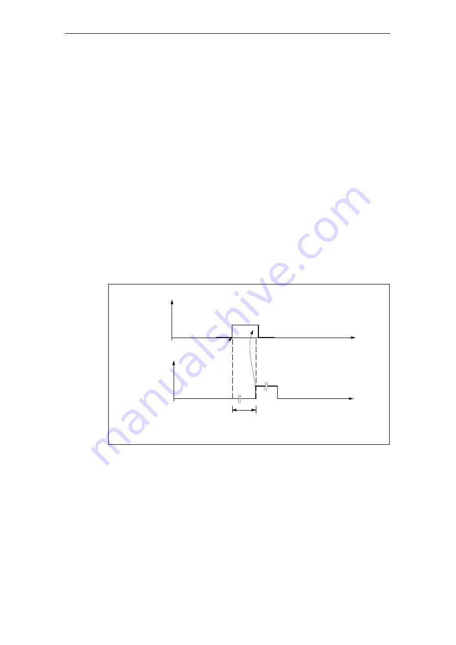
The mechanism for detecting and acknowledging an error is as follows:
S
The IM 178-4 detects a position encoder error and then sets the EXTF0,
EXTF1 or EXTF2 bit for the channel affected. This is only possible when none
of the bits EXTF0, EXTF1, EXTF2 of the affected channel is set at the time
when the error is detected and the group error acknowledgment EXTF_Q of the
channel has the value FALSE.
S
You can eliminate the indicated error and acknowledge it by assigning the value
TRUE to the EXTF_Q bit of the affected channel.
S
The module then clears the EXTF0, EXTF1 or EXTF2 bit belonging to the
position encoder error. When resetting the bit, the module does not check
whether the original position encoder error still exists nor whether another
position encoder error has occurred for this channel.
S
You assign the value FALSE to the EXTF_Q bit of the corresponding channel.
Following this, the module resumes error monitoring.
Status bit
EXTF0
Status bit
EXTF_Q
IM 178-4 detects
position encoder
error
LED SF
lights up
t
t
Figure 6-3
Handshaking Between the IM 178-4 and User Program When a Position
Encoder Error Occurs (Example EXTF0)
If a position encoder error occurs, the SF LED is lit until the error is eliminated and
you assign the value TRUE to the EXTF_Q bit of the affected channel.
If the error is eliminated in the Stop mode of the CPU (CLEAR mode), it does not
need to be acknowledged.


