8/12
16.04.1999
4 319 2697 0 c
Siemens Building Technologies / Landis & Staefa Division
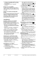
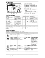
Schémas de raccordement
Pour alimentation basse tension
AC
2
3
0
V
B9
B3
B3
1
D1 D2
24
62
A
0
1
2
S1
24
6
2
A
0
2
24
62
A
0
3
3
B3
F3
T
c
Mesure de la température ECS par sonde (uniquement RVP210)
d
Contact externe pour commutation du régime
e
Mesure de la température ECS par thermostat (uniquement RVP210)
Pour alimentation secteur
24
64
A
0
4
AC
2
3
0
V
1
Q1
M3
Q3/Y3
F1/F4
F2
F3
2
F1/F4
F1
F2
E1
24
6
2
A
0
5
3
F1/F4
24
6
2
A
0
6
Y3
Q3/Y3
4
F3
24
6
2
A
0
7
c
Raccordement servomoteur trois points, pompe de circuit de chauffage et (uniquement RVP210) pompe de charge ECS
d
Raccordement brûleur (régulation de température de chaudière)
e
Raccordement servomoteur électrothermique (régulation de température de départ)
f
Raccordement servomoteur pour vanne de dérivation d'eau sanitaire (uniquement RVP210)
A6
Appareil d'ambiance QAW50 ou QAW70
B1
Sonde de température de départ ou de chaudière
B3
Sonde de température ECS (uniquement RVP210)
B9
Sonde extérieure QAC22 ou QAC32
E1
Brûleur
F1
Thermostat de chaudière
F2
Limiteur de température de sécurité
F3
Thermostat d'eau sanitaire (uniquement RVP210)
M1
Pompe de circuit de chauffage
M3
Pompe de charge ECS (uniquement RVP210)
N1
Régulateur RVP2...
S1
Contact externe
Y1
Servomoteur trois points
Y2
Servomoteur électrothermique
Y3
Servomoteur pour vanne de dérivation (uniquement RVP210)
en
English
Do not throw these instructions away but keep
them with the controller!
Only the RVP210 provides d.h.w. heating.
Installation
Place of installation
In a dry place, e.g. the boiler room.
Mounting choices:
-
In the control panel, on the inner wall or on a DIN
mounting rail
-
On a panel
-
In the control panel front
-
In the sloping front of a control desk
Permissible ambient temperature: 0…50 °C
Electrical installation
-
Local regulations on electrical installations must
be complied with
-
Cable tension relief must be assured
-
The cables from the controller to the actuator and
the pump carry mains voltage
-
The cables to the detectors should not be run
parallel to mains carrying cable (insulation class II
to EN 60730!)
Specifications of cable
Maximum permissible cable lengths to the detectors
and the room unit:
Copper cable 0.6 mm dia.:
30 m
Copper cable 0.5 mm
2
:
50 m
Copper cable 1.0 mm
2
:
80 m
Copper cable 1.5 mm
2
: 120
m


