Siemens Building Technologies / Landis & Staefa Division
4 319 2697 0 c
16.04.1999
11/12
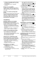
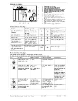
Commissioning the controller
1. Check wiring according to the plant connection
diagram.
2. Switch on power supply.
3. Check LED for "Override":
-
If it flashes, the detector wiring may be faulty
-
If it is lit, the controller is overridden by a re-
mote operation facility (room unit or changeo-
ver switch). Set room unit to operating mode
or open the external switch)
4. Set operating mode selector to .
5. Set heating curve potentiometer
to 4 and
setting knob to +8:
-
Flow temperature must rise: burner on, valve
open, heating circuit pump on (electro-thermal
actuators respond with a certain delay!)
-
If not: check wiring of the detectors
(flow/boiler, outside detector), actuator/burner
and heating circuit pump
6. Set operating mode selector to
.
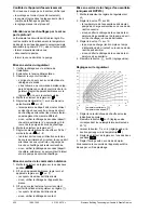
7. Set heating curve to 0.25 and setting knob to
–8.
-
Burner must switch off (observe minimum run-
ning time of 4 minutes), valve must travel to-
ward "colder", and heating circuit pump must
remain activated
-
If not: check wiring of the detectors
(flow/boiler, outside detector), actuator/burner
and heating circuit pump
Commissioning the remote operation
facility
1. Set the controller's operating mode selector to
one of the two
positions.
2. If a room unit is present: select operating mode
or
on the room unit.
-
Check the "Override" LED on the controller:
must be lit
-
If not: check wiring of the room unit
3. If a changeover switch is present: close it (gives
operating mode
on the controller).
-
Check the "Override" LED on the controller:
must be lit.
-
If not: check wiring of the changeover switch
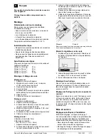
Commissioning of d.h.w. heating
(only RVP210)
1. The d.h.w. temperature must be around 30 °C
(check by touching or use a measuring instru-
ment).
2. Set the controller's operating mode selector
to
.
3. Set setting knob
to 60.
-
D.h.w. temperature must rise: charging pump
on or changeover valve open
-
If not: check wiring of the d.h.w. temperature
detector and the heating circuit pump, or the
changeover valve
4. Set setting knob
to 10 (observe overrun time)
-
Charging pump or changeover valve must
switch off
-
If not: check wiring of d.h.w. temperature de-
tector
5. Reset setting knob
to 55 (factory-setting).
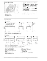
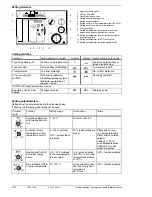
Settings on the controller
20
10
0
-10
-20
-30
90
80
70
60
50
40
30
4
3,5
3
2,75
2,5
2,25
2
1,75
1,5
1,25
1
0,75
0,5
0,25
100
24
62
D
0
1
T
V
T
A
110
20
T
A
Outside temperature [°C]
T
V
Flow temperature [°C]
1. Set heating curve as specified in the planning
documentation or in compliance with local prac-
tices.
2. Reset setting knob to 0 (factory-setting, cor-
responds to 20 °C room temperature).
3. Leave setting knob
to –6 (factory-setting).
4. Set operating mode selector to one of the two
positions.
5. Set time switch as indicated in the operating
instructions.
Seal the transparent cover, if required.


