15/16
Siemens Building Technologies
Data sheet RMH760
CE1N3131en
HVAC Products
03.07.2003
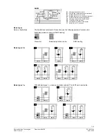
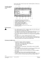
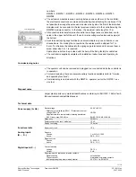
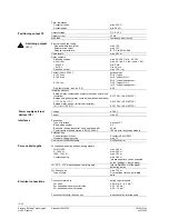
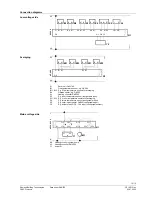
Connection diagrams
Low-voltage side
SP
M
SN
B1
B1
B
M
G
G0
N1
31
3
1A
01
M
X5
AC
2
4 V
X3
M
B9
B9
B
M
X3
M
B
X4
B
M
X4 M
X5
G8 M
G1 M
B7
Y9
Y9
G1 G0
CE-
CE+
A1
1
2
G1
Averaging
SP
M
SN
B1
B11
B
M
G
G0
31
31
A
03
AC
2
4 V
M
X3
B12
B
M
N1
X31
B
M
X32
B
M
A1
Room unit QAW740
B1
Flow temperature sensor, e.g. QAD22
B11, B12 E.g. 2 flow temperature sensors for averaging
B9
Outside sensor, e.g. QAC22
N1
Heating controller RMH760
X3
E.g. room temperature sensor (configurable input)
X31, X32 E.g. 2 room temperature sensors for averaging
X4
E.g. return temperature sensor (configurable input)
X5
E.g. solar impact sensor QLS60 (configurable input)
Y9
E.g. actuator with DC 0…10 V input (configurable output)
Y14
Y24
Y1
N
Y2
Y13
Y23
Y1
M1
Q14
Q74
Q72
Q13
Q71
A
C
24
...230 V
L
N
N1
31
31
A
0
2
N1
M1
Heating circuit or system pump
N1
Heating controller RMH760
Y1 Actuator
Mains voltage side

