11/16
Siemens Building Technologies
Data sheet RMH760
CE1N3131en
HVAC Products
03.07.2003
numbers:
RMH760 – RMZ781 – RMZ782 – RMZ782 – RMZ783 – RMZ786 – RMZ787 –
RMZ788.
•
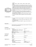
The extension modules require no wiring between one another or to the controller;
the electrical connections are made automatically when attaching the modules. If it is
not possible to arrange the extension modules side by side, the first of the detached
modules must be connected to the last previous module or to the controller using the
RMZ780 module connector. In that case, the maximum cable length is 10 m
•
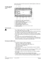
All connection terminals for protective extra low-voltage (sensors, data bus) are lo-
cated in the upper half of the unit, those for mains voltage (actuators and pumps) at
the bottom
•
Each terminal (spring cage terminal) can accommodate only one solid wire or one
stranded wire. For making the connections, the cables must be stripped for 7 to
8 mm. To introduce the cables into the spring cage terminals and to remove them, a
screw driver size 0 or 1 is required.
Cable strain relief can be provided with the help of the fixing facility for cable ties
•
The controller is supplied complete with Installation Instructions and Operating In-
structions
Commissioning notes
•
The operator unit can be removed and plugged in or connected while the controller is
in operation
•
For commissioning, there are several auxiliary functions available (refer to “Service
and operating functions”)
•
Commissioning is carried out with the RMZ79… operator unit or the OCI700.1 ser-
vice tool
Disposal notes
Larger plastic parts carry material identifications conforming to ISO/DIS 11 469 to facili-
tate environment-compatible disposal.
Technical data
Power supply (G, G0)
Rated voltage
−
Safety extra low-voltage (SELV) / Protective extra low-
voltage (PELV) to
−
Requirements for external safety isolating transformer
(100 % duty, max. 320 VA) to
AC 24 V
±
20 %
HD 384
EN 60 742 / EN 61 558-2-6
Frequency 50/60
Hz
Power consumption (excl. modules)
12 VA
Supply line fusing
10 A max.
Reserve of clock
12 h
Sensors
Passive
Active
1 or 2 LG-Ni 1000
DC 0…10 V
Signal sources
Passive
Active
0…2500
Ω
DC 0…10 V
Contact sensing
Voltage
Current
DC 15 V
5 mA
Requirements for status and impulse contacts
Signal
coupling
Type
of
contact
Insulating strength against mains potential
potential-free
maintained or impulse contacts
AC 3750 V to EN 60 730
Functional data
Analog inputs
(B…, X…)
Digital inputs (X…)
31
4
4Z
03
en
Low-voltage side
Mains voltage side

