s
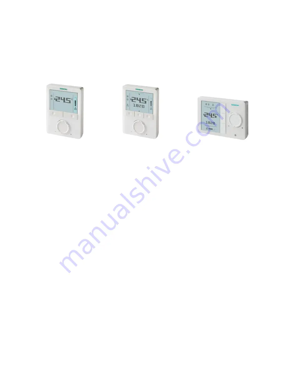
RDG100, RDG110, RDG110U
RDG100T, RDG160T, RDG160TU
RDG100T/H
Room thermostats with LCD for wall mountingRDG100RDG100TRDG110, RDG110URDG160T, RDG160TURDG100T/H
Basic Documentation
Edition 4.1
CE1P3181en2015-07-29
Building Technologies
Страница 1: ...DG110U RDG100T RDG160T RDG160TU RDG100T H Room thermostats with LCD for wall mounting RDG100 RDG100T RDG110 RDG110U RDG160T RDG160TU RDG100T H Basic Documentation Edition 4 1 CE1P3181en 2015 07 29 Building Technologies ...
Страница 2: ...res 20 4 6 1 Qx relay switching functions RDG160T only 25 4 7 Control sequences 26 4 7 1 Sequences overview setting via parameter P01 26 4 7 2 Control outputs configuration setting via DIP switches 4 5 and parameters 27 4 7 3 2 pipe fan coil unit 28 4 7 4 2 pipe fan coil unit with electric heater 29 4 7 5 2 pipe fan coil unit with radiator or floor heating 31 4 7 6 4 pipe fan coil unit 32 4 7 7 4 ...
Страница 3: ...ahrenheit 57 4 15 4 Parameters of the Expert level with diagnostics and test Degree Fahrenheit 58 4 15 5 Diagnostics and tests 60 5 Handling 61 5 1 Mounting and installation 61 5 2 Operation 63 5 3 Disposal 65 6 Engineering 66 6 1 Connection terminals 66 6 2 Connection diagrams 67 7 Mechanical design 72 7 1 General 72 7 2 Dimensions 73 8 Technical data 74 ...
Страница 4: ...I adaptations Several corrections 5 1 6 2 8 All 2 0 Dec 2011 Amendments concerning RDG100T H Adaptive temperature adaption electric heater Function specifications for units with SW V7 2 All 4 8 4 15 1 1 June 2009 Several small corrections All 1 0 May 2009 First edition 1 2 Reference documents Ref Document title Type of document Document no 1 Wall mounted room thermostats with LCD Data Sheet N3181 ...
Страница 5: ...st branch office The addresses of the Siemens Regional Companies are available at www siemens com sbt 1 3 3 Document use request to the reader Before using our products it is important that you read the documents supplied with or ordered at the same time as the products equipment applications tools etc carefully and in full We assume that persons using our products and documents are authorized and...
Страница 6: ...voltage RDG110 AC DC 24 V operating voltage RDG110U RDG160T DC 0 10 V or On Off control outputs for actuators DC 0 10 V or relay outputs for fan ECM or 1 3 speed AC DC 24 V operating voltage RDG100T RDG160T RDG100T H Infrared remote control receiver Auto Timer mode with 8 programmable timers Auto timer can be disabled via P02 Auto timer can be disabled via DIP switches RDG160T Landscape design onl...
Страница 7: ...to switch over between Comfort and Economy mode RDG100T RDG160T RDG100T H Infrared remote control RDG100T RDG160T RDG100T H Selectable relay function RDG160T For switching OFF external equipment OFF during Protection mode For switching ON external equipment e g pump during H C demand Output heating cooling sequence Wizard function to select working temperature unit C or F RDG160TU RDG110U 2 2 Type...
Страница 8: ...iator valves AC 24 V NO STA73 4884 Thermal actuator AC 230 V for small valves 2 5 mm 0 1 NC STP23 4884 Thermal actuator AC 24 V for small valves 2 5 mm 0 1 NC STP73 4884 Electrical actuator 3 position for radiator valves SSA31 4893 Electrical actuator 3 position for 2 and 3 port valves V P45 SSC31 4895 Electrical actuator 3 position for small valves 2 5 mm 0 1 SSP31 4864 Electrical actuator 3 posi...
Страница 9: ...used with On Off control signal 10 SFA SUA MVI MXI On Off actuators Parallel operation of SQS35 is not available Maximum number of actuators in parallel on the RDG110 10 On Off actuators Maximum number of actuators in parallel on the RDG160T 10 SS 61 actuators DC 10 ST 23 63 73 actuators DC or On Off 10 SFA SUA MVI MXI On Off actuators 10 SQS65 actuators DC 2 4 Accessories Description Product no D...
Страница 10: ...10 81 Siemens RDG100 RDG110 RDG160T Basic Documentation CE1P3181en Building Technologies Summary 2015 07 29 ...
Страница 11: ...ing system Chilled heated ceilings or radiators via On Off or modulating control outputs Chilled heated ceiling Chilled heated ceiling with electric heater Chilled heated ceiling and radiator floor heating Chilled heated ceiling 2 stage cooling or heating Heat pumps with dx type equipment 1 stage compressor for heating or cooling 1 stage compressor for heating or cooling with electric heater 1 sta...
Страница 12: ...temperature unit display on thermostats between C and F under the following two situations 1 Select the application via the DIP switches at the rear of thermostat before fitting the front housing to the mounting plate 2 Power up the thermostat after successfully connecting the line power Follow the steps 1 Rotate rotary knob to select the preferable temperature unit 2 Press the button OK to confir...
Страница 13: ...ternal operating mode switchover contact is active user operations are ineffective and OFF is displayed Control will then be according to Economy setpoints P11 and P12 In Protection mode the system is protected against frost factory setting 8 C 46 F can be disabled or changed via P65 protected against overheating factory setting OFF can be enabled or changed via P66 In Auto Timer mode AUTO the the...
Страница 14: ...the limit P10 then The setting range of cooling setpoint is from P09 40 C P09 104 F in place of 5 40 C 41 104 F The setting range of heating setpoint is from 5 P10 C 41 P10 F in place of 5 40 C 41 104 F This allows the user to limit the maximum heating setpoint and the minimum cooling setpoint This concept helps to save energy costs For 4 pipe applications The thermostat runs with the setpoint of ...
Страница 15: ...quence are the same w On 2 pipe applications with electric heater the Comfort setpoint is either at the first heating sequence in heating mode or at the cooling sequence in cooling mode On 2 pipe applications with radiator the Comfort setpoint is either at the radiator sequence in heating mode or at the cooling sequence in cooling mode The setpoints for Economy and Protection mode are below the Co...
Страница 16: ...of the dead zone between the heating and cooling sequence The dead zone can be adjusted via parameter P33 If manual changeover is selected then either the cooling sequence or the heating sequence is released In this case the Comfort setpoint is at the selected heating or cooling sequence Application Comfort mode Economy Protection mode Heating and Cooling Heating mode1 Cooling mode1 Heating and or...
Страница 17: ...pipe fan coil unit and radiator floor heating 1 2 3 4 5 ON OFF B1 M1 YHC T B2 T T B1 YHC M1 3076S02_01 T YE T B1 T B1 B2 B1 M1 YHC T B2 T T B1 YR Using RDG100 RDG110 RDG160T Using RDG100 RDG110 RDG160T Using RDG100 RDG110 RDG160T 2 pipe 2 stage fan coil unit 1 2 3 4 5 ON OFF 4 pipe fan coil unit 1 2 3 4 5 ON OFF 4 pipe fan coil unit and electric heater 1 2 3 4 5 ON OFF YHC1 M1 T B2 T B1 T B1 YHC2 ...
Страница 18: ... 3 4 5 ON OFF 3191S11 N1 T B1 T B2 T D3 YHC 3191S12 N1 T B1 T B2 T D3 YHC 3191S14 N1 T B1 T B2 T D3 YHC YR Using RDG100 RDG110 RDG160T Using RDG100 RDG110 RDG160T Using RDG100 RDG110 RDG160T 2 stage chilled heated ceiling 1 2 3 4 5 ON OFF Chilled ceiling and radiator 1 2 3 4 5 ON OFF YHC1 YHC2 3191S13 N1 T B1 T D3 YC YH Using RDG100 RDG110 RDG160T Using RDG100 RDG110 RDG160T Product no Control out...
Страница 19: ...10 RDG160T Product no Control outputs Fan RDG110 RDG110U On Off SPDT Disabled 3 speed 1 speed RDG160T RDG160TU On Off DC 0 10 V Disabled 3 speed 1 speed DC 0 10 V Legend YHC Heating cooling valve actuator M1 1 speed or 3 speed fan YH Heating valve actuator YC Cooling valve actuator B1 Return air temperature sensor or external room temperature sensor optional YE Electric heater B2 Changeover sensor...
Страница 20: ...te changeover Contact open heating mode Contact closed cooling mode The sensor or switch can be connected to input terminal X2 factory setting or X1 or D1 switch only depending on the commissioning of the inputs P38 P40 P42 See also section 4 10 for details The commissioning of the parameter Operating action P39 P41 P42 has in this case no effect The assignment is fixed Contact open heating mode C...
Страница 21: ... minute Readjusting the setpoint or heating cooling mode changeover immediately results in calculation of the output status output Y11 Y21 may not hold the minimum 1 minute On Off time If parameter P48 or P49 is set to above 1 minute the minimum On Off time for the control output is maintained as set even if the setpoint or changeover mode is readjusted This function is only available for On Off c...
Страница 22: ...l input to which the supply air sensor is connected needs to be set to Supply air sensor e g P38 9 Then the parameters for the limits are visible P63 minimum supply air temperature P64 maximum supply air temperature This function is only active in Comfort mode and can only be used with DC 0 10 V actuators For applications with electric heater and radiator this function is available only on the coo...
Страница 23: ...mporary Comfort mode extension sandglass symbol appears If parameter P68 extend Comfort period 0 extended Comfort cannot be activated pressing the left button will show OFF blinking 3 times The current operating mode can be forced temporarily into Comfort or Economy Protection mode The time period is adjusted via the rotary knob Extend presence Set the device to Comfort mode for the selected time ...
Страница 24: ...y Extension Comfort Economy Comfort or Economy Absence Economy Comfort Extension Absence functions not available in protection mode Function with time program RDG100T RDG100T H RDG160T User profile for operating mode selected via P02 Operating mode when activating function Function Operating mode during function Operating mode at the end of function P02 1 Auto or comfort Extension Comfort Auto Aut...
Страница 25: ... cooling demand the relay contact can be energized to control an external equipment for example to run the pump of a water system fan coil To reduce the wear and tear of the HVAC equipment the minimum output on time and off time of the Qx relay output can be adjusted from 1 to 20 minutes via parameters P48 and P49 The factory setting is 1 minute The relay output remains OFF if the heating is provi...
Страница 26: ...e Cooling heating sequence for electric heater radiator Manually select heating or cooling sequence using the button on the thermostat Automatic heating cooling changeover via external water temperature sensor or remote switch Heating and cooling mode i e 4 pipe 2 pipe 2 pipe and electric heater 2 pipe and radiator 4 pipe 4 pipe and electric heater 2 2 2 stage heating or cooling 1 Chilled heated c...
Страница 27: ...tion 2 position 3 position If 2 position is selected the factory setting is On Off If you want PWM pulse width modulation set parameters P46 and or P47 to 2 PWM With RDG110 only control output On Off is available With RDG160T the function of the control outputs DC 0 10 V or 2 position is set via parameters P46 and P47 Control output 1 P46 2 DC 0 10V signal Y10 terminal Factory setting P46 1 2 posi...
Страница 28: ...Heating mode Cooling mode T C Room temperature SDH Switching differential Heating P30 w Room temperature setpoint SDC Switching differential Cooling P31 YHC Control command Valve or Compressor Modulating control 3 position PWM or DC 0 10 V The diagrams below show the control sequence for modulating PI control Heating mode Cooling mode T C Room temperature XpH Proportional band Heating P30 w Room t...
Страница 29: ...is permanently disabled when manual changeover is selected P01 2 Remote enabling disabling of the electric heater is possible via input X1 X2 or D1 for tariff regulations energy savings etc Input X1 X2 or D1 must be commissioned accordingly parameters P38 P40 P42 See section 4 10 An electric heater must always be protected by a safety thermostat With a DC 0 10 V ECM fan it is possible to select On...
Страница 30: ...he control sequence for modulating control Heating mode automatic changeover heating or heating only Cooling mode man auto changeover cooling or cooling only Heating mode with manual changeover P01 2 on RDG100 and RDG110 manual changeover heating T C Room temperature W Room temperature setpoint YHC Control command Valve YE Control command Electric heater XpH Proportional band Heating P30 XpC Propo...
Страница 31: ... setpoint minus setpoint differential setpoint for fan coil unit The radiator sequence can also be used for floor heating The Floor heating limitation function is described on page 21 The diagrams below show the control sequence for 2 position control Heating mode Cooling mode T C Room temperature SDH Switching differential Heating P30 W Room temperature setpoint SDC Switching differential Cooling...
Страница 32: ...ing changeover sensor section 4 6 This mode is used for the so called Main and secondary application This is a 4 pipe fan coil unit system with different capacity of the 2 coils The water circuit is changed to optimize the energy exchange depending on the season summer winter Winter Large coil V1 for heating small coil V2 for cooling Summer Large coil V1 for cooling small coil V2 for heating T B1 ...
Страница 33: ...witching differential Cooling P31 Xdz Dead zone P33 Modulating control 3 position or PWM The diagrams below show the control sequence of modulating PI control Heating mode with manual selection P01 2 or for P09 P10 in heating sequence Cooling mode with manual selection P01 2 or for P09 P10 in cooling sequence Heating and cooling mode P01 04 T C Room temperature w Room temperature setpoint YH Contr...
Страница 34: ... regulations energy saving etc Input X1 X2 or D1 must be commissioned accordingly parameters P38 P40 P42 See section 4 10 for details An electric heater must always be protected by a safety thermostat The heating or cooling output can be released via operating mode button if parameter P01 is set to manual P01 2 See section 4 7 6 for details The diagrams below show the control sequence for 2 positi...
Страница 35: ...om temperature w Room temperature setpoint YE Control command Electric heater only On Off YH Control command Valve or Comp H only PWM not 3 position YC Control command Valve or Comp C XpH Proportional band Heating P30 XpC Proportional band Cooling P31 Xdz Dead zone P33 wD Setpoint differential P34 The diagrams only show the PI controller s proportional part Setting the sequence and the control out...
Страница 36: ...low setpoint minus setpoint differential In cooling mode the 1st stage is activated if the acquired temperature is above the setpoint The 2nd stage is activated if the acquired room temperature rises above setpoint plus setpoint differential The diagrams below show the control sequence for 2 position control Heating mode P01 0 Cooling mode P01 1 Changeover P01 2 or P01 3 T C Room temperature w Roo...
Страница 37: ...ating mode P01 0 Cooling mode P01 1 Changeover P01 2 or P01 3 T C Room temperature w Room temperature setpoint YHC1 Control command Stage 1 YHC2 Control command Stage 2 XpH Proportional band Heating P30 XpC Proportional band Cooling P31 Xdz Dead zone P33 wD Setpoint differential P34 The diagrams only show the PI controller s proportional part Setting the sequence and the control outputs Refer to s...
Страница 38: ...ooling 4 7 8 H H C C Refer to section 4 5 2 for details about the product type and control outputs 4 7 10 Compressor applications general For compressor applications set the corresponding basic application disable the fan P52 or set the fan speed P53 The following applications are available Minimum On Off time P48 P49 Fan operation P52 0 disabled 1 enabled Fan speed P53 1 1 speed 2 3 speed Refer t...
Страница 39: ...nect compressor and reversing valve as follows C1 RV ON OFF 1 2 3 This application is available with RDG110 only The diagrams below show the control sequences for 2 position control Heating mode with manual selection P01 2 Cooling mode with manual selection P01 2 Heating and cooling mode P01 04 T C Room temperature w Room temperature setpoint Y11 Control command Compressor H Y21 Control command Co...
Страница 40: ...ry setting 1 minute adjustable via parameter P48 OFF command when 1 the acquired room temperature is above the setpoint heating mode or below the setpoint cooling mode 2 the valve has been active for more than the Minimum output on time factory setting 1 minute adjustable via parameter P49 The electric heater receives an ON command via the auxiliary heating control output Y see Mounting Instructio...
Страница 41: ... to the control algorithm 2 When the thermostat calculates the positions fully close or fully open the actuator s running time is extended 150 to ensure the right actuator position is synchronized to the control algorithm 3 After the actuator reaches the position calculated by the thermostat a waiting time of 30 seconds is applied to stabilize the outputs This function is available with RDG100 RDG...
Страница 42: ...emperature and setpoint is provided via Y20 as a continuous DC 0 10 V signal The signal converter SEM61 4 converts the DC 0 10 V signal to AC 24 V PDM pulses for the current valve The current valve SEA45 1 supplies the electric heater with AC 50 660 V pulsed current For applications with ECM fan DC signal on RDG160T the electric heater can be controlled via the On Off output Q2 by setting P47 1 Ad...
Страница 43: ...tpoint the control valve closes and the fan switches off or stays at fan speed I minimum fan speed according to the setting of parameters P15 and P60 Factory setting for Fan in the dead zone Fan speed OFF P15 0 P60 OFF Only one fan output at a time is on either Q1 Q2 or Q3 The type of the fan output DC 0 10 V 3 speed or 1 speed can be set via DIP switch 4 local HMI P53 If application is set via DI...
Страница 44: ...witching point for low fan speed is synchronized to the heating cooling output Parameter Switching point fan speed low P57 is not relevant 2 The maximum switching range of the fan XpHFan XpCFan is defined by the switching differential SDH SDC via a look up table Heating Cooling 1 speed or 3 speed fan ECM fan Y Q3 Q2 Q1 T C Room temperature w Room temperature setpoint Q Fan speed Y Control command ...
Страница 45: ...peed Fan speed 3 III Max fan speed Xdz w T C Q 3191Z115_01 Fan_min Fan_max 100 0 Fan III Fan II Fan I Note The control signals Heating and Cooling are not influenced by the manual setting of fan speeds By heating only with electric heater manual fan speed 1 I cannot be selected to guarantee the necessary minimum air flow for the electric heater and to avoid overheating of the system For heating or...
Страница 46: ...a parameter P61 Fan kick value 0 means the fan runs continuously in the dead zone Fan kick value 1 and higher value in minutes Fan kick value OFF means the fan does not run in the dead zone Via parameter P15 in Service Level the fan speed in the dead zone in Comfort mode can be set according to customer preference The following options are available Fan does not run in the dead zone P15 0 Fan runs...
Страница 47: ...lly The function is set via parameter P62 default Off 0 The Clean filter reminder is reset when the operating mode is manually set to Protection and back In Auto Timer mode the default fan mode is automatic The fan mode can be changed to Manual by pressing the FAN button The fan returns to the automatic default mode after each switchover from Comfort to Economy mode and vice versa To let the heati...
Страница 48: ...ode switchover contact is active user operations are ineffective and OFF is displayed DI DI 4 Dewpoint monitor Digital input for a dewpoint sensor to detect condensation Cooling is stopped if condensation occurs DI DI 5 Enable electric heater Digital input to enable disable the electric heater via remote control DI DI 6 Fault Digital input to signal an external fault example dirty air filter If th...
Страница 49: ...nking 3 Turn the rotary knob clock or counterclockwise to set the time of day If the current time of day is in 24 hour format and you wish to change it to 12 hour format turn the knob clockwise passed 23 59 or counterclockwise passed 00 00 If the current time of day is in 12 hour format and you wish to change it to 24 hour format turn the knob clockwise passed 12 00 pm or counterclockwise passed 1...
Страница 50: ...irm by pressing button OK 5 Weekday and blink Press button OK to select or button Esc to deselect each day and advance to the next day 6 After the 7th day is adjusted all selected weekdays blink Confirm setting for actual timer by pressing button OK and advance to the next timer To adjust the next timer repeat step 3 6 or press button Esc to leave the setting mode To save your adjustments remember...
Страница 51: ...fault timer settings 1 Press the program mode button twice to select the Auto timer setting in programming mode 2 Press button OK to enter the timer setting mode 3 Press the program mode button for at least 3 seconds rES will be displayed 4 Press button OK to confirm reloading of the default timer settings or button Esc to leave without change The display shows 8888 during the reloading process Wh...
Страница 52: ...otely Select Protection Comfort or Auto Timer mode Adjust setpoint in Comfort mode Select fan mode Automatic or Manual A buzzer in the thermostat indicates remote control command reception Infrared remote control can be disabled via parameter P70 4 14 DIP switches Use the DIP switches at the rear of the thermostat to commission the thermostat s basic application prior to snapping it to the base Th...
Страница 53: ...within 2 seconds until the display shows P01 Continue with step 2 1 Press left button and right button simultaneously for 4 seconds Release and press the left button again within 2 seconds until the temperature disappears Turn the rotary knob counterclockwise min rotation The display shows Pxx Continue with step 2 2 Select the required parameter by turning the rotary knob 3 Press button OK the cur...
Страница 54: ... Auto Prot x x x x P04 Selection of C or F 0 C 0 degrees Celsius C 1 degrees Fahrenheit F P05 Sensor calibration internally externally 0 K 3 3 K P06 Standard temperature display 0 0 room temperature 1 setpoint P07 Display info line 2nd line of LCD 0 0 no display 1 C and F 0 1 x x 0 1 x P08 Comfort setpoint 21 C 5 40 C P09 Min setpoint for Comfort mode 5 C 5 40 C P10 Max setpoint for Comfort mode 3...
Страница 55: ...igital input NO NO normally open open NC normally closed closed P40 P42 Functionality of D1 3 operating mode changeover 0 no function 2 H C changeover DI 3 operating mode contact DI 4 dewpoint sensor DI 5 enable electric heater DI 6 fault input DI 0 6 0 6 0 6 0 6 0 6 P43 Operating action of D1 if digital input NO NO normally open open NC normally closed closed P42 P44 Running time of Y1 Y2 output ...
Страница 56: ...in Comfort mode time until next kick OFF 0 89 min OFF P52 P61 Fan kick interval in Economy mode time until next kick OFF 0 359 min OFF P52 P62 Clean filter reminder running time OFF 0 OFF 100 9900 hours P52 P63 Minimum supply air temperature OFF OFF 0 P64 C x x x x P38 P40 P64 Maximum supply air temperature OFF OFF 0 P64 C x x x x P38 P40 P65 Protection heating setpoint 8 C OFF 5 W Cool Prot W Coo...
Страница 57: ... C or F Depends on Wizard setting 0 degrees Celsius C 1 degrees Fahrenheit F P05 Sensor calibration internally externally 0 F 6 6 F P06 Standard temperature display 0 0 room temperature 1 setpoint P07 Display info line 2nd line of LCD 0 0 no display 1 C and F 0 1 x P08 Comfort setpoint 70 F 41 104 F P09 Min setpoint for Comfort mode 41 F 41 104 F P10 Max setpoint for Comfort mode 95 F 41 104 F P11...
Страница 58: ...9 P41 Operating action of X2 if digital input NO NO normally open open NC normally closed closed P40 P42 Functionality of D1 3 operating mode changeover 0 no function 2 H C changeover DI 3 operating mode contact DI 4 dewpoint sensor DI 5 enable electric heater DI 6 fault input DI 0 6 0 6 P43 Operating action of D1 if digital input NO NO normally open open NC normally closed closed P42 P45 Power of...
Страница 59: ...100 9900 hours P52 P63 Minimum supply air temperature OFF OFF 32 P64 F x P38 P40 P64 Maximum supply air temperature OFF OFF P63 122 F x P38 P40 P65 Protection heating setpoint 8 C OFF 41 W Cool Prot W Cool Prot 104 F max P66 Protection cooling setpoint OFF OFF W Heat Prot 104 F W Heat Prot 41 F min P67 Fan start delay RDG110U RDG160TU 0 s 0 180 s 0 360 s P52 P46 P47 P68 Extension Comfort period OF...
Страница 60: ...0 H C input closed 100 H C input open d05 Test mode for checking actuator direction Y1 Y2 press left button to escape no signal at outputs Y1 and Y2 OPE output Y1 forced opening CLO output Y2 forced closing x x P46 d06 Test mode for checking actuator direction Y3 Y4 press left button to escape no signal at outputs Y3 and Y4 OPE output Y3 forced opening CLO output Y4 forced closing x x P47 d07 Soft...
Страница 61: ...0 V mains or AC 24 V supply line must have a circuit breaker with a rated current of no more than 10 A For AC 24 V US installations use Class 2 rated power supplies Properly size the cables to the thermostat fan and valve actuators for AC 230 V mains voltage Use only valve actuators rated for AC 230 V on RDG100 RDG110 and on RDG160T if AC 230 V is connected to the L terminal Use only 3 speed fan r...
Страница 62: ...it is not selected C is used by default The control sequence may need to be set via parameter P01 depending on the application The factory setting for the 2 pipe application is Cooling only and Heating and cooling for the 4 pipe application When the thermostat is used in connection with a compressor the minimum output on time parameter P48 and off time parameter P49 for Y11 Y21 must be adjusted to...
Страница 63: ...into Operating mode selection Press left button 3 seconds Set thermostat to Protection mode Keep left button depressed and turn rotary knob clockwise Activate temporary timer Extend presence and set the time for details see page 23 Keep left button depressed and turn rotary knob counterclockwise Activate temporary timer Extend absence and set the time for details see page 23 Press left button whil...
Страница 64: ...III 6 Auto Timer mode 17 Degrees Celsius Degrees Fahrenheit 7 View and set auto timer program 8 Protection 18 Digits for room temperature and setpoint display 9 Escape 19 Button lock 10 Digits for time of day room temperature setpoint etc 20 Condensation in room dewpoint sensor active 11 Setting the time of day and the weekday 21 Weekday 1 7 1 Monday 7 Sunday 12 Morning 12 hour format Afternoon 12...
Страница 65: ...15 07 29 5 3 Disposal The devices are considered electronics devices for disposal in terms of European Directive 2012 19 EU and may not be disposed of as domestic waste Dispose of the device via the channels provided for this purpose Comply with all local and currently applicable laws and regulations ...
Страница 66: ...eed medium Q3 Control output fan speed high Y1 Y4 Control output Valve AC 230 V NO for normally open valves output for electric heater via external relay Y11 Y21 Control output Valve AC 230 V for RDG110 Control output Valve AC 24 V for RDG110U NO for normally open valves output for compressor or electric heater Y12 Y22 Control output Valve AC 230 V for RDG110 Control output Valve AC 24 V for RDG11...
Страница 67: ...ating cooling radiator heating cooling 1 st or 2 nd stage S1 S2 Switch keycard window contact etc S3 Switch at SELV input keycard window contact B1 B2 Temperature sensor return air temperature external room temperature changeover sensor floor temperature limit etc Q Relay outputs Y1 Y4 Triac outputs YH Heating valve actuator YC Cooling valve actuator YHC Heating cooling valve actuator YR Radiator ...
Страница 68: ...re external room temperature changeover sensor floor temperature limit etc Q Relay outputs Y11 Y22 Relay outputs YH Heating valve actuator YC Cooling valve actuator YHC Heating cooling valve actuator YR Radiator valve actuator YE Electric heater max 5 A YHC1 YHC2 1 st 2 nd stage C1 C2 Compressor 1 st and 2 nd stage RV Reversing valve 1 speed or 3 speed fan Application V1 V2 2 pipe YHC 2 pipe and r...
Страница 69: ...erature limit etc Q Relay outputs Y11 Y22 Relay outputs YH Heating valve actuator YC Cooling valve actuator YHC Heating cooling valve actuator YR Radiator valve actuator YE Electric heater max 5 A YHC1 YHC2 1 st 2 nd stage C1 C2 Compressor 1 st and 2 nd stage RV Reversing valve 1 speed or 3 speed fan Application V1 V2 2 pipe YHC 2 pipe and radiator 4 pipe 2 stage YHC YH YHC1 YR YC YHC2 2 pipe and ...
Страница 70: ...Compressor 1 st 2 nd stage M1 1 speed or 3 speed fan DC 0 10 V fan V1 V2 Valve actuators On Off DC 0 10 V heating cooling radiator 1 st or 2 nd stage YH Heating valve actuator YC Cooling valve actuator YHC Heating cooling valve actuator YR Radiator valve actuator YHC1 YHC2 1 st 2 nd stage max 1 mA G L G 10A M1 Y50 max 5 4 A G0 G0 X1 M X2 V1 B2 S2 B1 S1 Q1 Q2 Q3 D1 GND S3 Y10 Y20 max 1 mA M1 max 5 ...
Страница 71: ...DC 0 10 V fan V1 V2 Valve actuators On Off DC 0 10 V heating cooling radiator 1 st or 2 nd stage YH Heating valve actuator YC Cooling valve actuator YHC Heating cooling valve actuator YHC1 YHC2 1 st 2 nd stage For US installations use Class 2 rated power supplies For other installations use circuit breakers with rated current of no more than 10 A max 1 mA G C G M1 Y50 max 5 4 A G0 G0 X1 M X2 V1 B2...
Страница 72: ...room thermostat consists of 2 parts Plastic housing which accommodates the electronics the operating elements and the temperature sensor Mounting plate with the screw terminals The housing engages in the mounting plate and is secured with 2 screws on the left side RDG100 RDG110 RDG110U RDG100T RDG160T RDG160TU RDG100T H For operation refer to section 5 2 ...
Страница 73: ... 93 0 3 66 28 2 1 11 27 8 1 09 28 5 1 12 16 0 0 63 9 0 0 35 28 3 1 11 27 7 1 09 4 0 0 16 4 0 0 16 30 8 1 21 28 3 1 11 28 3 1 11 28 3 1 11 28 3 1 11 mm inch 128 0 5 04 93 0 3 66 28 5 1 12 30 8 1 21 mm inch 3181M02 28 2 1 11 27 8 1 09 16 0 0 63 9 0 0 35 28 3 1 11 27 7 1 09 28 3 1 11 4 0 0 16 4 0 0 16 28 3 1 11 28 3 1 11 28 3 1 11 RDG1 RDG100T H ...
Страница 74: ...rotection with max C 10 A circuit breaker in the supply line required under all circumstances Multifunctional inputs X1 M X2 M Temperature sensor input Type Temperature range Cable length Digital input Operating action Contact sensing Parallel connection of several thermostats for one switch Insulation against mains D1 GND Operating action Contact sensing Parallel connection of several thermostats...
Страница 75: ...24 V AC 5 mA 5 3 A No internal fuse External preliminary protection with max C 10 A circuit breaker in the supply line required under all circumstances Multifunctional inputs X1 M X2 M Temperature sensor input Type Temperature range Cable length Digital input Operating action Contact sensing Parallel connection of several thermostats for one switch Insulation against mains D1 GND Operating action ...
Страница 76: ...r control Q1 Q2 Q1 rating min max resistive inductive Q2 rating min max resistive inductive Max total load current Q1 Q2 Q3 5 mA 1 A 5 mA 5 4 A 5 A Use for external equipment Q1 Q2 Q3 Rating min max resistive inductive Qx Max total load current Q1 Q2 Q3 5 mA 1 A 2 A No internal fuse External preliminary protection in L line with max C 10 A circuit breakers required in all cases ECM fan control Y50...
Страница 77: ... 2 Operating mode switchover P42 3 Built in room temperature sensor Measuring range Accuracy at 25 C 77 F Temperature calibration range 0 49 C 32 120 F 0 5 K 1 F 3 0 K 6 F Settings and display resolution Setpoints Current temperature value displayed 0 5 C 1 F 0 5 C 1 F Operation Climatic conditions Temperature Humidity As per IEC 60721 3 3 Class 3K5 0 50 C 32 122 F 95 r h Transport Climatic condit...
Страница 78: ... packaging environmental benefit disposal Connection terminals Solid wires or prepared stranded wires 1 x 0 4 2 5 mm2 14 gauge or 2 x 0 4 1 5 mm2 16 gauge Note For sensors on inputs X1 X2 or D1 the cable length is max 80 m 262 feet Wiring cross section on L N Q1 Q2 Q3 Y1 Y2 Y3 Y4 Y11 Y21 Min 1 5 mm2 16 gauge Housing front color RAL 9003 white Weight RDG100 RDG110 RDG160T 0 30 kg 0 32 kg The docume...
Страница 79: ...gs 50 Dewpoint monitor 47 Dewpoint monitoring 21 Diagnostics and test 52 Digital input 47 DIP switches 51 Disposal 64 E ECM fan 44 ECM Ventilator 7 Economy mode 12 Electric heater 28 Enable disable electric heater 28 33 47 Expert level parameters 52 Extend Comfort mode 22 Extension of presence absence 22 External return air temperature 47 External return air temperature sensor 19 F Fan in Auto Tim...
Страница 80: ... PWM 39 PWM for electric heater 40 R Radiator 30 Radiator applications 37 Reloading default timer settings 50 Remote heating cooling changeover 19 Resetting parameters 52 Reversing valve 38 S Sensor input 47 Setpoint Comfort mode 14 Setpoint Economy mode 14 Setpoint limitation 13 Setpoint Protection mode 14 Setpoints and sequences 14 Setting the time of day and the weekday 48 Setting the timers 49...
Страница 81: ...ies 2015 07 29 Siemens Switzerland Ltd Building Technologies International Headquarters Gubelstrasse 22 CH 6301 Zug Tel 41 41 724 24 24 Fax 41 41 724 35 22 www buildingtechnologies siemens com 2009 Siemens Switzerland Ltd Subject to change ...