Siemens MAMMOMAT NovationDR Скачать руководство пользователя страница 62

PXCM Web Tool 

February 5, 2004 


5-11 

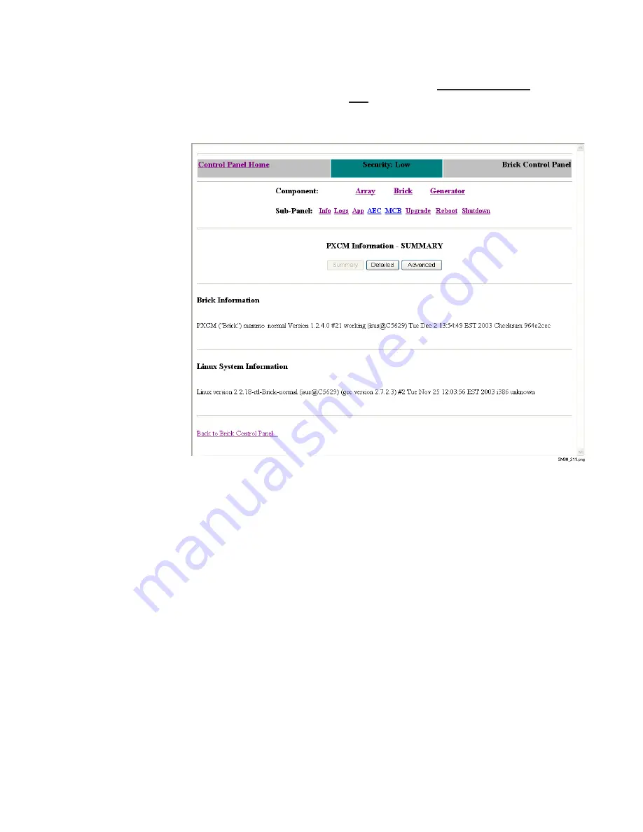
Viewing Information About the PXCM

To view information about the PXCM,

 click the Information/Status link on the 

Brick Control Panel page, or the Info link on any of the other PXCM pages. The 

PXCM Information - Summary page displays.

To view more detailed PXCM information, click the 

Detailed 

button. A sample of 

the PXCM detailed information is shown on the following page.

Содержание MAMMOMAT NovationDR

Страница 1: ...duction transmission or use of this document or its contents is not permitted without express written authority Offenders will be liable for damages All rights including rights created by patent grant or registration of a utility model _or_ design _are_ reserved SP FFDM S Service Manual DRC Installation Instructions ...

Страница 2: ...DirectRay for Siemens Full Field Digital Mammography FFDM S Service Manual Direct Radiography Corp February 5 2004 Document No MAN 00190 ...

Страница 3: ...of Direct Radiography Corp The information in this document is subject to change without notice Copyright 2004 by Direct Radiography Corp All rights reserved Printed in the U S A DirectRay is a registered trademark of Direct Radiography Corp All other trademarks registered trademarks and product names used within this document are the property of their respective owners Direct Radiography Corp 600...

Страница 4: ...garding Small Detail Object Imaging 1 3 Restrictions on Use 1 3 Detector Safety and Compliance Information 1 4 Environment 1 4 Certification 1 4 Classification 1 4 Warnings Cautions and Notes 1 5 Symbols Used 1 6 PXCM Safety and Compliance Information 1 7 Environment 1 7 Certification 1 7 Classification 1 7 Warnings and Cautions 1 7 Chapter 2 Theory of Operation Normal Operations Sequence 2 1 Comm...

Страница 5: ... Information and Exiting the Tool 4 3 Main Window Functions and Options 4 3 Determining the Half Value Layer HVL 4 5 Determining the Entrance Skin Exposure ESE 4 8 Generating the Goal Image 4 11 Copying Goal Images 4 13 Chapter 5 PXCM Web Tool When PXCM Web Functions Should Be Used 5 1 Opening the PXCM Web Tool Home Page 5 1 Function Security Levels and Login Prompts 5 2 Detector Functions 5 3 Vie...

Страница 6: ...idelines General Troubleshooting Guidelines 7 1 Interpreting Results from PXCM Self Test 7 1 Interpreting the PXCM Status LEDs 7 2 Reporting DirectRay Log Information 7 2 Chapter 8 Replacement Replacement Guidelines 8 1 Packing a DirectRay Detector for Shipment 8 2 Appendix A Specifications DirectRay Detector PXCM and Interface Card General Specifications A 1 Electrical A 2 DirectRay Detector A 2 ...

Страница 7: ...vi February 5 2004 FFDM S Service Manual THIS PAGE IS INTENTIONALLY BLANK ...

Страница 8: ...nents during exposures It also describes the DirectRay technology used in the DirectRay Detector Chapter 3 Installation Provides guidelines for installing the hardware components of the DirectRay FFDM S system Chapter 4 Calibrating the AEC Describes how to calibrate the AEC by generating a goal table for a desired target filter combination and loading it into the DirectRay Power and X ray Control ...

Страница 9: ...of special messages to emphasize information or point out potential risks to personnel or equipment A sample of each message type follows NOTE Notes provide additional information such as expanded explanations hints or reminders CAUTION Cautions point out procedures that you must follow precisely to avoid damage to equipment loss of data or corruption of files in software applications WARNING Warn...

Страница 10: ...onverts X rays into digital data The DirectRay Power and X ray Control Module PXCM which acts as the interface between the generator the DirectRay Detector and the FFDM S Acquisition Workstation software The DirectRay Interface card a PCI card located in the Acquisition Workstation which provides the fiber optic cable connection between the PXCM and the Acquisition Workstation These components are...

Страница 11: ...use of X ray equipment IEC Regulations Software used in the DirectRay FFDM S system was developed using IEC 60601 1 4 as a guide Manufacturer s Responsibility This equipment is sold with the understanding that Direct Radiography Corp its agents and representatives do not accept any responsibility for overexposure of patients or personnel to X radiation Furthermore Direct Radiography Corp does not ...

Страница 12: ...e the contrast of a single spherical object the same size as a pixel would have a different appearance if the object were imaged directly overlying a detector element highest contrast or placed at the intersection of four detector elements lowest contrast Objects inherently smaller than individual pixels will have a lower apparent contrast because of the digital sampling of the analog radiation in...

Страница 13: ...in accordance with the appropriate IEC 601 1 and or IEC 601 1 1 harmonized national standard Otherwise use within the defined Patient Vicinity is not approved Testing of the FFDM S in combination with the end use equipment shall include leakage current test ground continuity tests temperature tests and other tests as required by the appropriate standards The maximum operating temperatures of certa...

Страница 14: ...sed in this product may be damaged by static electricity or electrostatic discharge Unpack and handle using appropriate precautions CAUTION Each image detector is provided with a CD ROM containing data for initial gain calibration and defect mapping The gain calibration process must be performed again when installed at the end user site to compensate for variations in the specific x ray tube breas...

Страница 15: ...ray cleaning solution directly on the equipment Instead moisten cloth with the solution and wipe the Detector Fragile Handle with care Do not immerse the equipment in liquid This product contains no user serviceable parts Assembly of this product is done under controlled clean room conditions Exposing the more sensitive internal parts lesser environments may permanently affect product performance ...

Страница 16: ...the appropriate standards The maximum operating temperatures of certain safety components as defined in the applicable safety standards must not be exceeded in the end use installation to maintain the intended safety The PXCM S is intended to be installed within X ray equipment and serviced only by persons trained and approved to work on that specific equipment using the appropriate tools Classifi...

Страница 17: ...Inc regarding their GSM28 5 power supply When performing Dielectric Strength Tests catastrophic failure of the unit may result if a Dielectric Strength test voltage greater than 1800 Vac is applied between primary and secondary circuits The components providing isolation from primary to secondary cannot be tested while installed in the power supply without overstressing basic primary to ground ins...

Страница 18: ...components during exposures It also describes the DirectRay technology used in the DirectRay Detector Normal Operations Sequence A flowchart of the normal workflow is illustrated in Figure 2 1 on page 2 2 Understanding the normal operation of the system facilitates troubleshooting to isolate the possible causes of problems ...

Страница 19: ...ient Technologist Acquires Image Technologist Adjusts Image Technologist Modifies Technique Factors Technologist Confirms Patient Identity on Acquisition Workstation Technologist Selects Existing Procedure from List Technologist Selects New Procedure from List Is the Procedure Listed Technologist Modifies the Exam Settings Technologist Accepts Image Adjust Accept No No Reject No No Yes Yes Yes No ...

Страница 20: ...is also referred to as the brick Therefore you will see the terms PXCM and brick used interchangeable throughout this topic Additional Information About AEC Mode During AEC mode 1 A 5 mAs pre exposure is made 2 The actual mAs of the pre exposure is sent from the Generator to the PXCM in a code S message 3 The PXCM collects the resulting pixel values binned together in super pixels 128 x 128 pixels...

Страница 21: ...ends exposure data to brick Brick Request post exposure data msg t_det_rdy t_rotor_ok DR_SYST_RDY_ t_det_rdy_from_boost t_det_cycle t_gen_msg_dly t_boost_to_query t_gen_rdy_to_query t_expose X_RAY_ON_ t_grid_dly t_dly_from_exp_finished t mess exch DR_DET_ERR_ GEN_POWERED_ON_ X ray button activated Acc anode Inactivation after exposure termination Code A Code C Code X Code Z t_prep_end_dly t_gen_rd...

Страница 22: ...k Brick Request post exposure data msg t_det_rdy t_rotor_ok DR_SYST_RDY_ t_det_rdy_from_boost t_det_cycle t_gen_msg_dly t_boost_to_query t_gen_rdy_to_query t_expose X_RAY_ON_ t_grid_dly t_dly_from_exp_finished t mess exch DR_DET_ERR_ pre exp Code A Code B Code C t aec setup GEN_POWERED_ON_ X ray button activated Acc anode Inactivation after exposure termination Code X Code C Code Y CodeZ t_prep_en...

Страница 23: ...ator to PXCM The Generator is ready to expose Activation When the anode speed is reached the signal is activated Deactivation The Generator deactivates the signal when The exposure buttons are released A correctly terminated exposure has been proceeded GEN_RDY_FOR_DR_EXP_ Generator to PXCM Deactivation The Generator deactivates the signal when An error interrupts the exposure For timing requiremen...

Страница 24: ...ignal DR_SYST_RDY is activated Deactivation When the signal GEN_RDY_FOR_DR_EXP_ is deactivated the signal DR_SYST_RDY_ is deactivated For timing requirements see t_dly_from_exp_finished DR_DET_ERR PXCM to Generator An error is present in the DirectRay system Activation When there is an error condition within the DirectRay system the signal is activated Deactivation When the error condition has bee...

Страница 25: ...or example a photoconductor material is used as the X ray absorption material In a process known as direct conversion charges are generated by the X ray interactions in the semiconductor and are collected and converted to a digital signal Refer to Figure 2 4 The advantage of this process is that there is no need to produce an intermediate resolution degrading signal such as light Figure 2 4 Compar...

Страница 26: ...analog electronics that perform the data capture and conversion into digital format An 8 bit micro controller in the DirectRay Detector performs the management functions of setup monitoring and control of the acquisition electronics Figure 2 5 DirectRay Detector Structure INTERNAL DETECTOR COVER X RAY CONVERSION LAYER DETECTOR TFT MATRIX SUPPORT STRUCTURE READOUT CHARGE AMPLIFIERS READOUT GATE DRI...

Страница 27: ...rspective View of DirectRay Detector Multi Layer Structure The storage capacitor and charge collection electrode are configured in such a way that the electrode forms a mushroom head over much of the detector element area This unique design is illustrated in Figure 2 7 on page 2 11 The mushroom electrode Shields the FET from the high electric field that is generated by the high voltage applied to ...

Страница 28: ...y isolate the detector Electronic Readout The readout of the charges starts immediately at the end of the X ray exposure While all FETs which are operated here as simple on off switches are not conducting during the X ray exposure a positive gate pulse applied to the first gate line simultaneously turns on all FETs connected to the first gate line This causes the image charge to flow to a bank of ...

Страница 29: ...2 12 February 5 2004 FFDM S Service Manual This Page Left Intentionally Blank ...

Страница 30: ... the bucky and the PXCM in the X ray tower 3 Connect the PXCM to the Detector using the appropriate cable 4 Connect the PXCM to the Generator using the appropriate cable 5 Install the DirectRay Interface PCI card in the Acquisition Workstation then connect the PXCM to the Interface card using fiber optic cable 6 Calibrate the Automatic Exposure Control AEC Guidelines for installing the DirectRay h...

Страница 31: ...to return the DirectRay Detector to Direct Radiography Corp To unpack the DirectRay Detector 1 Open the box and remove the packing insert 2 Remove all of the other packing material covering the inner box in which the Detector is packaged GS20_414 cdr Open box and remove top packing insert Remove packing inserts and phase change material shown here in gray GS20_415 cdr ...

Страница 32: ... inner box which includes the temperature logger that is used to ensure that the Detector maintained the proper temperature will being shipped and stored GS20_416 cdr Lift out inner box by pulling on lifting band do not cut the band GS20_417 cdr Open box remove packing insert temperature logger and phase change material Lift out Detector and carefully remove from wrapper Temperature logger Slide l...

Страница 33: ...e care Avoid touching the thin film top cover that protects the imaging area The imaging electronics under the front cover are extremely sensitive The actual image area starts at the front edge and is approximately 25 mm inside the other three edges Any dust or fingerprints in this area may affect final image quality Temperature extremes may cause permanent damage ...

Страница 34: ...mammography equipment using four M6 threaded fasteners Figure 3 1 DirectRay Detector Fastener Hole Locations Figure 3 2 shows the Detector connector used for the cable that connects the Detector to the DirectRay PXCM Figure 3 2 DirectRay Detector Connector for cable to PXCM IMAGING AREA GS20_411 cdr Connector for cable to DirectRay PXCM ...

Страница 35: ...use Figure 3 3 DirectRay PXCM Stud Hole Locations Figure 3 4 shows the PXCM connectors used for the cable that connects the Detector to the DirectRay PXCM and the fiber optic cable to the DirectRay Interface card Figure 3 4 DirectRay PXCM Connectors for cable to Detector and fiber optic cables to Interface card GS20_412 cdr Connector for cable to DirectRay Detector Fiber optic connectors to Direct...

Страница 36: ...refer to the hardware installation instructions that accompany the Acquisition Workstation Figure 3 5 shows the Interface card fiber optic connectors used for the cable that connects the PXCM to the Interface card Figure 3 5 DirectRay Interface Card Fiber Optic Connectors for fiber optic cable to PXCM GS20_413 cdr Connectors for fiber optic cables to DirectRay PXCM shown with cap on left connector...

Страница 37: ... housing insert the cable connector into the connector on the device making sure to align the keying features so the connectors are properly mated then turning the connector clockwise to lock it To disconnect the cable connector turn it counterclockwise then pull it from the connector on the device Cleaning Clean the connectors on both the cable and the devices with a lint free alcohol dampened cl...

Страница 38: ...alid mAs value and using that value take a series of exposures to generate goal images TheAEC Calibration Tool averages the goal images to in turn generate and load a goal table into the PXCM There are three calibration procedures which are performed in sequence 1 Determining the Half Value Layer HVL of the X ray Generator for a given target filter combination described in Determining the Half Val...

Страница 39: ...n Workstation operating system as apps The FFDM S Acquisition Workstation application must not be running If the application is running kill it using the task manager If you are logging in as apps then immediately upon the desktop being displayed double click the console window icon and press the Ctrl C keys You must do this within 5 seconds to prevent the FFDM S Acquisition Workstation applicatio...

Страница 40: ...of the X ray Generator for a given target filter combination For the procedure for determining the HVL refer to Determining the Half Value Layer HVL on page 4 5 Determine ESE Select this procedure to determine the Entrance Skin Exposure ESE This step may be performed without determining the HVL of the X ray Generator However a valid HVL value must be known For the procedure for determining the ESE...

Страница 41: ...or image capture If the Status Window is green and displays DRAPI Armed it is not necessary to use this button This button will only work when the status window is yellow and displays DRAPI Ready Clicking on this button will clear the Radiation Entry field Units Use this to select the radiation units to be used Choices are R mR or Gy mGy When this selection is changed the AGD setting will change t...

Страница 42: ...e a 0 4 mm thickness of Aluminum For the Molybdenum target and Rhodium filter use 0 5 mm For the Tungsten target and Rhodium filter use a 0 6 mm thickness of Aluminum The result of the HVL procedure is a fractional number representing the HVL in millimeters of Aluminum NOTE If you already know the HVL and want to proceed with determining the ESE value go to Determining the Entrance Skin Exposure E...

Страница 43: ... button As the DirectRay Detector and DRAPI recycle for the next exposure the Status will change from DRAPI Armed to DRAPI Not Ready and will turn from green to white When the DRAPI is ready to be enabled for the next exposure the Status will again say DRAPI Ready and will be yellow Instructions for the next exposure display 7 Perform the displayed instructions The amount of aluminum added in this...

Страница 44: ...e 15 In the Reading field enter the dosimeter value in the appropriate units 16 Make sure the entry is correct then click the Submit button When the DRAPI is ready to be enabled for the next exposure the Status will again say DRAPI Ready and will be yellow Instructions for the final HVL exposure step display 17 Perform the displayed instructions 18 Click the Enable Capture button The last dosimete...

Страница 45: ...GD This in turn suggests the mAs that should be used to generate the goal table To determine the mAs value 1 In the tool s main window select the desired AGD value before starting the ESE determination Once the first ESE exposure has been performed the AGD value cannot be changed 2 Select the Determine ESE procedure option If the tool has the HVL value stored internally for example you just perfor...

Страница 46: ... are selected 7 Repeat steps 5 and 6 for the second and third ESE exposures After the third exposure the average of the three dosimeter values entered is displayed Also the suggested mAs value to be used for goal table generation is displayed NOTE In most cases the suggested mAs will not exactly match an mAs value to which the Generator can be set In this case it is recommended that you use the cl...

Страница 47: ...4 10 February 5 2004 FFDM S Service Manual ...

Страница 48: ...ing the procedure you will choose the number of goal images 1 to 4 to average together for the final result The tool instructions will prompt you to enable capture and expose for each of the images When the final image exposure is complete the tool will automatically generate the goal table with a name derived from the target filter combination used The goal table will then automatically be loaded...

Страница 49: ...The text scrolling in the initial command window will show the following text NOTE The text messages may be interspersed with DRAPI image frame messages Also the sample messages shown below represent a selected AGD of 1 5 mGy Binning the goal image to make goaltab file goaltab1 for Mo Mo target filter Reading image file done Generating binned image done Writing AEC image 448x512 file done Writing ...

Страница 50: ...he load OK message be assured that the goaltab has been stored in the PXCM s long term storage and will be auto installed on reboot Simply reboot the PXCM before attempting to take AEC exposures For information on rebooting the PXCM refer to Rebooting the PXCM on page 5 21 Copying Goal Images You can copy an existing goaltab file to the PXCM under another name To copy the goaltab file to the PXCM ...

Страница 51: ...4 14 February 5 2004 FFDM S Service Manual This Page Left Intentionally Blank ...

Страница 52: ...ly by Direct Radiography Corp or only when Direct Radiography Corp s Support staff directs you to use them in the course of troubleshooting system problems Restrictions regarding a function s use is covered in its topic in this chapter Opening the PXCM Web Tool Home Page To open the PXCM Web Tool s home page from a web browser running on the Acquisition Workstation enter the following in the URL f...

Страница 53: ... will be displayed to verify that they have authority to use the function Low security indicated by a green background These functions can be used without affecting the related component s operation Moderate security indicated by a yellow background These functions could affect the related component s operation but changes would not adversely affect its operation High security indicated by a red b...

Страница 54: ...pting to use it during the same PXCM web tool session Detector Functions NOTE The DirectRay Detector is also referred to as the Array Therefore you will see the term Array used for Detector throughout the web tool and the topics in this chapter The Detector functions are accessible from the Array Control Panel page To display the Array Control Panel page click either of the Array links on the home...

Страница 55: ...ual Viewing Information About the Detector To view information about the Detector click the Information Status link on the Array Control Panel page or the Info link on any of the other Array pages The Array Information Summary page displays ...

Страница 56: ...ry 5 2004 5 5 To view a listing of the Detector files click the Array Files button A list of Detector files displays as shown below Some file names are links clicking on one of these links displays the contents of the file ...

Страница 57: ...ibed in Table 5 1 NOTE For security purposes you may be prompted to enter a login name and password before executing this function For more information refer to Function Security Levels and Login Prompts on page 5 2 Table 5 1 Advanced Search and Detailed Log Page Operations To Do This View the current active log Click the Summary button Search for a text string in the current active log and displa...

Страница 58: ...The following screen shot shows an example of the current active log listing displayed by clicking the Summary button To return to the Advanced Search and Detailed Log Info page from the active log listing page click the Detailed button ...

Страница 59: ...oftware page displays NOTE For security purposes you may be prompted to enter a login name and password before executing this function For more information refer to Function Security Levels and Login Prompts on page 5 2 2 Select the software component that you want to upgrade 3 Click the Browse button then navigate to and select the appropriate software component file from your Acquisition Worksta...

Страница 60: ...ng the Detector refer to Powering the Detector On and Off on page 5 9 Powering the Detector On and Off To power the Detector on or off or reboot it click the Array Power Control link on the Array Control Panel page or the Power link on any of the other Array pages The Array Power Control page displays Click the appropriate button for the operation that you want to perform NOTE For security purpose...

Страница 61: ... from the Brick Control Panel page NOTE The PXCM is also referred to as the brick Therefore you will see the terms PXCM and brick used interchangeable throughout the web tool and the PXCM topics in this chapter To display the Brick Control Panel page click either of the Brick links on the home page ...

Страница 62: ... PXCM click the Information Status link on the Brick Control Panel page or the Info link on any of the other PXCM pages The PXCM Information Summary page displays To view more detailed PXCM information click the Detailed button A sample of the PXCM detailed information is shown on the following page ...

Страница 63: ...button for displaying even more detailed information However this advanced information is intended only as an aid to Direct Radiography Corp Support staff in troubleshooting PXCM problems For this reason you will typically be using this function only at the direction of Direct Radiography Corp Support ...

Страница 64: ...phy Corp Support To view PXCM log files click the Log File s link on the Brick Control Panel page or the Logs link on any of the other PXCM pages The Advanced Search and Detailed Log Info page displays The operations you can perform from this page are described in Table 5 1 on page 5 6 NOTE For security purposes you may be prompted to enter a login name and password before executing this function ...

Страница 65: ...ual The following screen shot shows an example of the current active log listing displayed by clicking the Summary button To return to the Advanced Search and Detailed Log Info page from the active log listing page click the Detailed button ...

Страница 66: ... link on the Brick Control Panel page or the App link on any of the other PXCM pages The Brickman Status page displays NOTE For security purposes you may be prompted to enter a login name and password before executing this function For more information refer to Function Security Levels and Login Prompts on page 5 2 CAUTION The Brickman page also includes an Execute Command button and an Advanced b...

Страница 67: ...ck the Brick AEC Configuration link on the Brick Control Panel page or the AEC link on any of the other PXCM pages The Brick AEC Status page displays as shown on the next page NOTE For security purposes you may be prompted to enter a login name and password before executing this function For more information refer to Function Security Levels and Login Prompts on page 5 2 CAUTION The Brick AEC page...

Страница 68: ...PXCM Web Tool February 5 2004 5 17 ...

Страница 69: ...t To view MCB firmware information click the Brick Firmware link on the Brick Control Panel page or the MCB link on any of the other PXCM pages The MCB page displays NOTE For security purposes you may be prompted to enter a login name and password before executing this function For more information refer to Function Security Levels and Login Prompts on page 5 2 CAUTION The MCB page includes an Adv...

Страница 70: ...are file to transfer field NOTE To clear your file selection click the Reset Form button 3 When you are ready to start the firmware file transfer click the Upgrade Now button The file transfer status is displayed on the page 4 After the transfer is complete reboot the PXCM to have it start up using the firmware you just transferred For information refer to Rebooting the PXCM on page 5 21 CAUTION T...

Страница 71: ...he other PXCM pages The Upgrade PXCM Software page displays NOTE For security purposes you may be prompted to enter a login name and password before executing this function For more information refer to Function Security Levels and Login Prompts on page 5 2 2 For the Select the package to be upgraded option select siemens 3 Select whether you want to overwrite all of the PXCM configuration files I...

Страница 72: ...s displayed on the page 8 After the transfer is complete reboot the PXCM to have it start up using the software you just transferred For information about rebooting the PXCM refer to Powering the Detector On and Off on page 5 9 Rebooting the PXCM To reboot the PXCM click the Reboot the Brick link on the Array Control Panel page or the Reboot link on any of the other PXCM pages You will be prompted...

Страница 73: ... Array Control Panel page or the Shutdown link on any of the other PXCM pages You will be prompted to confirm the shutdown operation NOTE For security purposes you may be prompted to enter a login name and password before executing this function For more information refer to Function Security Levels and Login Prompts on page 5 2 ...

Страница 74: ... February 5 2004 5 23 Generator Functions The Generator functions are accessible from the Generator Control Panel page To display the Generator Control Panel page click either of the Generator links on the home page ...

Страница 75: ...more detailed Generator information click the Detailed button A sample of the Generator detailed information is shown on the next page NOTE The Generator Information page also includes an Advanced button for displaying even more detailed information However this advanced information is intended only as an aid to Direct Radiography Corp Support staff in troubleshooting Generator problems For this r...

Страница 76: ...PXCM Web Tool February 5 2004 5 25 ...

Страница 77: ... these functions only at the direction of Direct Radiography Corp Support To view Generator configuration information click the Configure Generator link on the Generator Control Panel page or the Config link on any of the other Generator pages The Generator Configuration Status page displays NOTE For security purposes you may be prompted to enter a login name and password before executing this fun...

Страница 78: ...nerator Configuration Modify Settings page displays 2 Select the Duration of Change option to specify how long you want the new scan timeout value to be in effect NOTE To clear your selection and entry click the Reset button 3 In the Scan Timeout Value field enter the timeout value in seconds 4 To save your modifications click the Change Scan Timeouts button ...

Страница 79: ...rvice functions are accessible from the Factory Service Control Panel page To display the Factory Service Control Panel page click the Factory Service link on the home page The summary information is displayed on the page The page also includes a listing of the available logs To save the PXCM run time statistics to an archive tar and compressed file click the Brick Run Time Stats link From the dia...

Страница 80: ...mall differences in their performance can result in differences in the X ray densities detected for the same amount of X ray Performing calibration allows the system to detect these small differences along with other variables that can affect the digital signal output The system can then apply adjustments to the output data to compensate for these differences When to Calibrate the DirectRay Detect...

Страница 81: ...ng tables provide direction for cause and corrective action for those artifacts that have been validated as coming from DirectRay components For troubleshooting questions contact Direct Radiography Corp Support Table 6 1 Line Artifacts Problem Cause Recommended Action Line Parallel to the Short Axis Seam Seam correction algorithm not turned on wrong algorithm selected Detector gain not calibrated ...

Страница 82: ...One or More 256 Blocks usually more pronounced on an edge Electromagnetic noise interfering with Detector Read Out Shield Motors power sources and so on located in proximity to the DirectRay Detector Table 6 4 Other Artifacts Problem Cause Recommended Action Density Image is too dark or light Verify LUT curves are properly set No Image or Very High Exposure Required to Obtain an Image HV setting i...

Страница 83: ...6 4 February 5 2004 FFDM S Service Manual This Page Left Intentionally Blank ...

Страница 84: ... This chapter explains the diagnostic and troubleshooting guidlines for the DirectRay FFDM S components General Troubleshooting Guidelines THIS TOPIC STILL UNDER DEVELOPMENT Interpreting Results from PXCM Self Test THIS TOPIC STILL UNDER DEVELOPMENT ...

Страница 85: ...the PXCM If this LED does not light for a significant amount of time that is 2 to 3 minutes reboot the PXCM V3 Power status A green LED that lights to indicate that the PXCM is providing power to the Detector Figure 7 1 DirectRay PXCM Status LEDs Location Reporting DirectRay Log Information You may be asked by your central service support group to submit DirectRay log information related to a prob...

Страница 86: ...ector DirectRay PXCM DirectRay Interface card Cables There are no field reparable units If one of these components fail you should replace the component with a new one and ship the failed component back to Direct Radiography Corp For information on how the DirectRay components are secured and connected refer to Chapter 3 You may also have to reinstall DirectRay Detector or Power and X ray Control ...

Страница 87: ...ed To pack the Detector for shipping 1 Locate the original packing material in which the Detector was shipped prior to installation and place the Detector in its protective bag 2 Place the Detector in its bag the temperature logger the packing insert and the phase change material into the inner box as shown below Slide the lifting band over the box ...

Страница 88: ...Replacement February 5 2004 8 3 3 Place the inner box the phase change material and packing inserts in the outer box as shown below ...

Страница 89: ...8 4 February 5 2004 FFDM S Service Manual 4 Place the large packing insert between the inner and outer boxes as shown below 5 Tape the box closed ...

Страница 90: ...Ray Detector Width X cm X in Height X cm X in Depth X cm X in DirectRay PXCM Width X cm X in Height X cm X in Depth X cm X in DirectRay Interface Card Width X cm X in Height X cm X in Depth X cm X in Image Area Full field Y x Y cm Y x Y in nominal active image area Detector Pixel X µm Y x Y µm active element size Y x Y detector element matrix Y geometric fill factor Presampling MTF X at Y Y cycles...

Страница 91: ...tRay Detector is shipped in an approved insulated shipping container Maximum gradient X C X F per hour assuming the unit is stored in an approved shipping container Relative humidity X to X allow condensation dry time before installing Maximum gradient X per hour Temperature 20 to 35 C 68 to 95 F Maximum gradient X C X F per hour Relative humidity 10 to 80 non condensing Maximum gradient X per hou...

Страница 92: ...Connection Signal Detector PXCM Connector X601 Pins EL power EL power com P R 24vdc 24com S V 24vdc 24com W X 24vdc 24com T U GND L GND H Data Shield Data Data C D J Serial Shield Xmit Xmit Recv Recv N A E M K Bot EL ON F spare spare no connection no connection A K M G W E T N C H P U F B R V X L J D ...

Страница 93: ...5P 2 GEN_RDY_FOR_DR_EXP_ DB25P 3 DR_DET_RDY_FOR_EXP_ DB25P 4 DR_SYST_RDY_ DB25P 5 DR_DET_ERR_ DB25P 6 GEN_POWERED_ON_ DB25P 7 X_RAY_ON_ DB25P 8 spare DB25P 9 RxD DB25P 10 TxD DB25P 11 GEN_ 5V_232 DB25P 12 X ray equipment supplies 5 Vdc to power its side of the optocouplers spare DB25P 13 No connection GND_CTRL DB25P 14 to 21 spare DB25P 22 GND_232 DB25P 23 to 25 ...

Страница 94: ...bruary 5 2004 B 1 B Field Replaceable Units Part No Description FFDM S DirectRay Full Field Digital Mammography Detector PXCM S DirectRay Power and X ray Control Module DRIC S DirectRay Interface Card PCI ...

Страница 95: ...B 2 February 5 2004 FFDM S Service Manual This Page Left Intentionally Blank ...

Отзывы: