Siemens Building Technologies
CM2N4625E / 02.1999
Landis & Staefa Division
7/10
•
Functional check:
Control signal AC 24 V
– between wires 1-6 : Actuator turns clockwise.
– between wires 1-7 : Actuator turns counter clockwise.
Control signal AC 230 V
– between wires 6-4 : Actuator turns clockwise.
– between wires 7-4 : Actuator turns counter clockwise.
The actuator remains in its current position if no control signal is applied.
•
Position indication by measuring the potentiometer resistance while the actuator turns
from 0...90°.
•
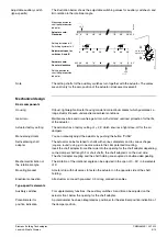
Switch the auxiliary switch contacts "A" and "B" while the actuator reaches the
respective switching positions.
The auxiliary switches are factory set:
Switch A:
Switching point at 5°
Switch B:
Switching point at 85°
To change the settings of A and B, use a flat blade screwdriver to turn the switch
adjustment dials to the desired setting.
The angle values are valid only for the actuator position "0°" (clockwise direction).
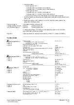
Power supply AC 24V
for
GIB131.1E
GIB135.1E
GIB136.1E
Operating voltage
Control signal AC 24 V (wires 1-6), clockwise
Control signal AC 24 V (wires 1-7), counter clockwise
Safety extra-low voltage (SELV) or
protection by extra-low voltage (PELV) as per
Protection class
Requirements for external safety insulating transformer (100% duty) to
Feeder protection external
Frequency
Power consumption: running actuator
holding (economy function)
AC 24 V +
20 %
HD 384
III as per EN 60 730
EN 60 742
max. 10 A
50/60 Hz
10VA/10 W
1VA/0.5 W (after > 200 s)
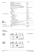
Power supply AC 230V
for
GIB331.1E
GIB335.1E
GIB336.1E
Operating voltage
Control signal AC 230 V (wires 6-4), clockwise
Control signal AC 230 V (Wires 7-4), counter clockwise
Protection class
Feeder protection external
Frequency
Power consumption: turning actuator
holding (economy function)
AC 230 V +
10 %
II as per EN 60 730
max. 10 A
50/60 Hz
13 VA/10 W
6 VA/0.5 W (after > 200 s)
Auxiliary switches
for
GIB135.1E
GIB136.1E
GIB335.1E
GIB336.1E
Contact rating
Life:
6 A resistive, 2 A inductive
5 A resistive, 1 A inductive
no load
Voltage
Protection class
Voltage proof auxiliary switch to housing
Setting range for switchover contacts
Setting increments
Switching hysteresis
Factory setting:
Switch A
Switch B
6 A resistive, 2 A inductive
10
4
switchings
5 x 10
4
switchings
10
6
switchings
AC 24...230 V
II as per EN 60 730
AC 4 kV
5°...85°
5°
2°
5°
85°
Positioners
(Potentiometer) for
GIB135.1E
GIB335.1E
Resistance change (wires P1-P2)
Load
maximum sliding contact current
Protection class
Voltage proof potentiometer to housing
0...1000
Ω
< 1 W
< 10 mA
III as per EN 60 730
AC 500 V
Connection cables
Power supply AC 24 V (wires 1, 6, 7) / AC 230 V (wires 4, 6, 7)
Auxiliary switches A and B (wires S1...S6)
Potentiometer (wires P1, P2, P3)
3 x 0.75 mm
2
6 x 075 mm
2
3 x 0.75
mm
2
Factory settings for
auxiliary switches A and B
(see "Technical design")
Important
Technical data

