background image

CM2N4625E / 02.1999

Siemens Building Technologies

6/10

Landis & Staefa Division

All information and steps to properly prepare and mount the actuator are listed in the
Mounting Instruction guide M4626 delivered with the actuator. The shaft adapter as well
as all other individual parts are not pre-mounted as the actuator components are put
together differently depending the damper shaft length. Refer to "Mechanical design" in
this data sheet.

Select the mounting position so that you can easily access the cables as well as the
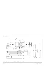
setting dials on the front of the actuator. Refer to "Dimensions".

In order to satisfy the requirements as per IP54, the following mounting conditions must
be fulfilled:

• 

Mount the actuators only vertically (cabling see below) for air dampers with horizontal
shafts.

• 

When the actuator is mounted directly on the damper shaft, the mounting angle my be
a maximum of  +/- 45 °.

• 

Use the ASK75.1 weather shield for mounting in any other position.

If you mount the actuator directly on the damper shaft, the mounting bracket must be
used.  The insertion depth for the shaft into the housing must be sufficient and
guaranteed.

Information on minimum length and diameter for the damper shaft is listed in "Technical
data".

The actuator comes with a factory setting of + 2,5° which ensures a tight close-off for
the air dampers.

To ensure a tight close-off function for the dampers and the exact switching position for
switches A and B, the actuator can only be adjusted with a mounted shaft adapter and
position indicator in accordance with the mounting instructions.

If necessary, you can limit the rotational angle in increments of 5° for the entire span by
positioning the shaft adapter in the respective position.

The mounting sets which are used to change the rotational movement into a linear
stroke as described in "Type summary" are mounted separately.

All information necessary for commissioning is contained in the following:

• 

This data sheet 4625

• 

Mounting instructions M4626

• 

Job diagram

Check to ensure that all permissible values as contained in "Technical data" are
observed.

• 

Check for proper mounting and to ensure that all mechanical settings are in
accordance with the plant-specific requirements. Additionally, ensure that the
dampers are shut tight when in the closed position.

• 

Fasten the actuator securely to avoid side load.

• 

Check the rotation direction: The dampers must be able to be moved by pushing the
button "PUSH”.

• 

Check to ensure that the cables are connected in accordance with the plant wiring

diagram (see "Diagrams").

• 

The operating voltage AC 24 V (SELV/PELV) or AC 230 V must be within the
tolerance values.

Mounting notes

Mounting instructions

Mounting position

Housing protection

Mounting bracket

Damper shafts

Actuator factory setting

Manual adjustment

Mechanical limitation of
the rotational angle

Using the mounting sets

Commissioning
notes

References

Environmental conditions

Mechanical check

Electrical check

Содержание GIB131.1E

Страница 1: ...rollers or ON OFF controls e g outside air dampers flue gas dampers etc The actuator s rotational movement clockwise or counterclockwise depends on the electrical control As soon as the operating voltage AC 24 V or AC 230 V is applied the actuator starts to turn The connected damper can be operated as follows via the respective actuator control Damper opens 0 90 Damper closes 90 0 Damper remains i...

Страница 2: ...ious mounting options depending on the direction of rotation and shaft length separate parts such as the shaft adapter with position indicator and other mounting parts are shipped separately with the actuator The actuator comes with 0 9 m long pre wired connection cables The following accessories and spare parts are available for function upgrades of the actuators see data sheet N4699 Accessories ...

Страница 3: ...pers You can manually adjust the actuator by pushing the button PUSH The actuator can be fastened to shafts with various diameters and in various shapes square round using just one screw due to the L G patented mounting Insert the shaft adapter from either side into the opening for the shaft adapter depending on the damper shaft length For short shafts the shaft adapter is on the duct side The sha...

Страница 4: ...er 4 Connection cable for power supply 5 Connection cable for auxiliary switches 6 Gear train disengagement button 7 8 Adjustment dials for auxiliary switches A and B 9 Position indicator 10 Self centering shaft adapter 11 Locking ring for shaft adapter 12 Adapter for position indicator 13 Mounting bracket 4626Z23 10 11 4626Z25 9 4626Z22 11 12 10 4626Z24 9 Setting and operating elements Arrangemen...

Страница 5: ... is within the required tolerance Voltage drops at the feed lines must be included Electric parallel connection of these actuators is possible only via relay if used with types GDB 3 1 GLB 3 1 SQE3 SQE8 SQR3 or SQR8 Mechanical Do not mechanically couple the actuators The quantity of actuators required depends on several torque factors After obtaining the damper torque rating Nm m2 from the manufac...

Страница 6: ... the dampers and the exact switching position for switches A and B the actuator can only be adjusted with a mounted shaft adapter and position indicator in accordance with the mounting instructions If necessary you can limit the rotational angle in increments of 5 for the entire span by positioning the shaft adapter in the respective position The mounting sets which are used to change the rotation...

Страница 7: ...ower consumption running actuator holding economy function AC 24 V 20 HD 384 III as per EN 60 730 EN 60 742 max 10 A 50 60 Hz 10VA 10 W 1VA 0 5 W after 200 s Power supply AC 230V for GIB331 1E GIB335 1E GIB336 1E Operating voltage Control signal AC 230 V wires 6 4 clockwise Control signal AC 230 V Wires 7 4 counter clockwise Protection class Feeder protection external Frequency Power consumption t...

Страница 8: ...onditions Operation Climatic conditions Mounting location Temperature Humidity non condensing IEC 721 3 2 Class 2K2 32 70 C 95 r h Class 2M3 IEC 721 3 3 Class 3K5 inside weather protected 32 55 C 95 r h IP Code Housing type according to EN 60 529 IP 54 Conformity In accordance with the directives set forth by the European Union Electromagnetic compatibility EMC Low voltage directive 89 336 EEC 73 ...

Страница 9: ...ormally open contact gray pink Q14 S4 Switch B Input black red Q21 S5 Switch B Normally closed contact black blue Q22 S6 Switch B Normally open contact black pink Q24 Positioner P1 Potentiometer 0 100 P1 P2 white red a P2 Potentiometer pick off white blue b P3 Potentiometer 100 0 P3 P2 white pink c 4626A01 Y1 G G0 SP SN AC 24 V GBB13 1 S2 S3 S5 S6 7 P3 S1 S4 Y 6 P1 P2 Y2 N AC 24 V SELV PELV N Regu...

Страница 10: ...a Division min 7 300 73 85 8 m a x 9 5 900 min 100 min 60 min 200 20 10 230 4 2 67 5 3 4626M01 100 27 6 ø 5 7 15 197 max 20 P1 P3 1 7 S1 S6 Taptite M6 x 16 13 1 5 GCA 1 GBB 1 GIB 1 Ø 8 25 6 mm 6 18 mm Dimensions Dimensions in mm 1999 Siemens Building Technologies Ltd ...

Отзывы: