BA 5814 en 09/2014
6.3
Shaftmounted gear unit with hollow shaft and shrink disk
The end of the drivenmachine shaft (material C60+N or higher strength) should have a centring means
to DIN 332 Form DS (with thread) in its end face (for connecting dimensions of the drivenmachine shaft,
see dimensioned drawing in the gearunit documentation).
6.3.1
Fitting
•
Remove the corrosion protection from the hollow shaft and machine shaft with a suitable cleaning
agent.
The cleaner must not be allowed to come into contact with the shaftsealing rings.
Ensure adequate ventilation. Do not smoke.
Danger of explosion!
•
Check the hollow and machine shafts to ensure that seats and edges are not damaged. If necessary,
rework the parts with a suitable tool and clean them again.
The bore of the hollow shaft and the machine shaft must be absolutely free of grease
in the area of the shrinkdisk seat.
This is essential for safe and reliable torque transmission.
Do not use contaminated solvents or dirty cloths for removing grease.
Observe manufacturer’s instructions for handling lubricants and solvents.
6.3.1.1 Fitting
•
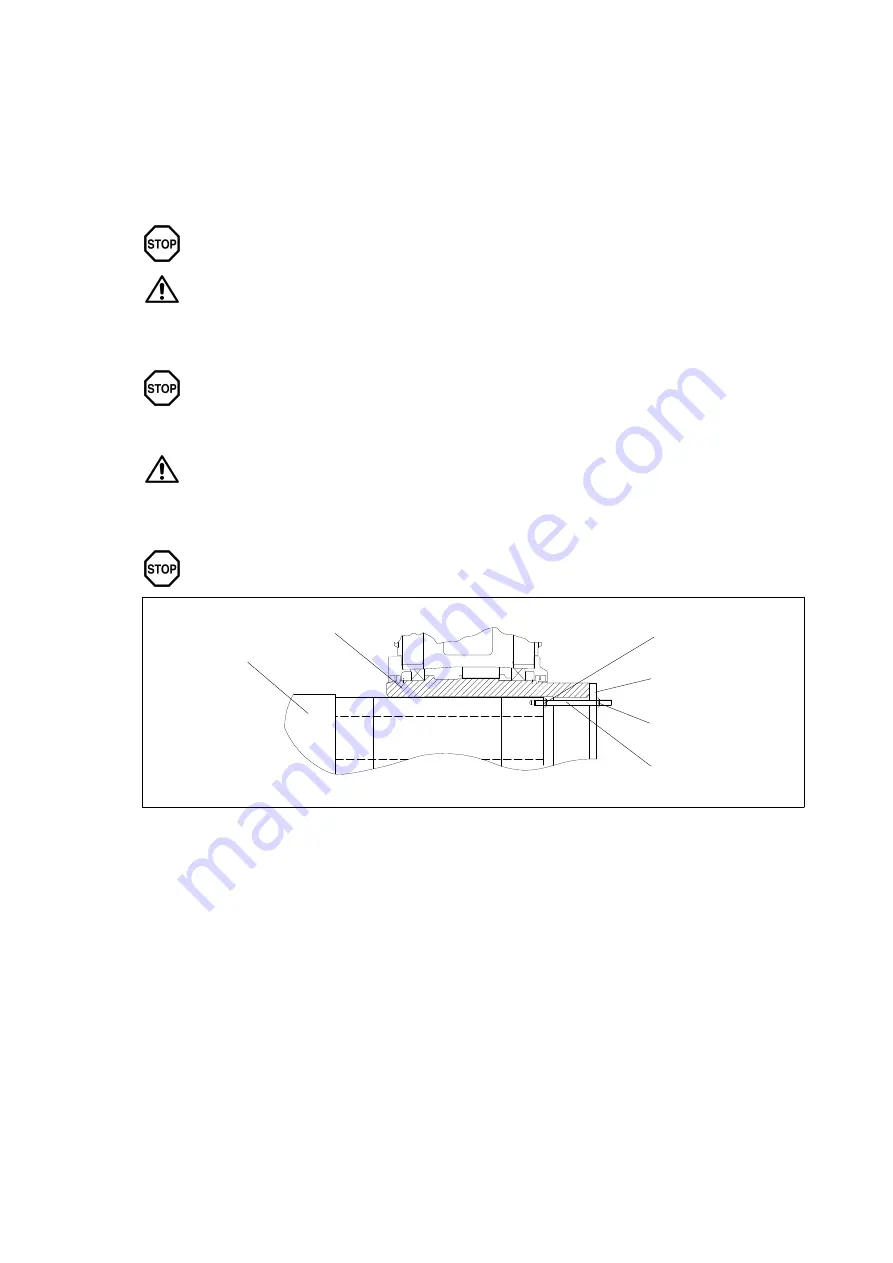
Fit the gear unit by means of nut and threaded spindle. The counterforce is provided by the hollow shaft.
The hollow shaft must be exactly aligned with the machine shaft to avoid canting.
5
6
4
3
2
1
Fig. 15:
Fitting
1
Machine shaft
4
Threaded spindle
2
Hollow shaft
5
Nut
3
Nut
6
End plate
Instead of the nut and threaded spindle shown in the diagram, other types of equipment such as a hydraulic
lifting unit may be used.
6.3.1.2 Axial fastening
If the shrink disk is fitted according to instructions, the gear unit is fixed securely in the axial direction.
Additional axial fastening is not required.


