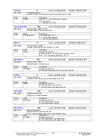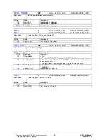
GPIO2_ IN
R
Addr.: 0x4000_2528 Default: Port assignment
Description
Input register for General Purpose IO [44:32]
Bit No.
Name
Description
31..13 Reserved
Reserved
12..0
GPIO2_IN[44:32]
0: GPIO inputx = 0, 1: GPIO inputx = 1
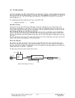
4.3 Timer
0/1/2
Three independent timers are integrated in the ERTEC 200. They can be used for internal monitoring of diverse software
routines. Each timer is assigned an interrupt that is connected to the IRQ interrupt controller of the ARM946. Access to
these 3 timers is always 32 bits in width.
4.3.1
Timer 0 and Timer 1
Both timers have the following functionality:
32-bit count register
Input clock can be switched to:
50 MHz clock (default setting)
8-bit prescaler per timer (can be assigned separately)
Down-counting
Load/reload
function
Start, stop and continue functions
Interrupt when counter state 0 is reached
Count register can be read/write-accessed
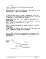
The timers 0 / 1 are deactivated after reset. The timers are enabled by setting the “RUN/XStop” bit in the status/control
register of the respective timer. The timer then counts downwards from its loaded 32-bit starting value. When the timer
value reaches 0, a timer interrupt is generated. The interrupt can then be evaluated by the IRQ interrupt controller.
Depending on the reload mode, the two timers behave as follows:
•
Reload mode = 0 The corresponding time stops when attaining the value = 0.
•
Reload mode = 1 The corresponding timer is reloaded with the 32-bit reload value and automatically restarted.
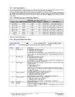
The timer can also be reloaded with the reload value during normal timer function (count value ! = 0). This occurs by
setting the “LOAD” bit in the status/control register of the timer.
Normally, the timer clock operates at 50 MHz, which is generated by the internal PLL. Each timer can also be operated
with an 8-bit prescaler. This can be used to increase the timer time accordingly.
Copyright © Siemens AG 2007. All rights reserved.
38
ERTEC 200 Manual
Technical data subject to change
Version 1.1.0


