background image

Creating Project Files—SEAbus Port Expander

Siemens Energy & Automation, Inc.

 45

6 Creating Project Files—SEAbus 

Port Expander

This chapter covers configuration of the DTU3005 as a
SEAbus port expander. Once you have created a SEA-
bus port expander project (see 

Chapter 3

), follow the

directions in this chapter to configure the project file.
Then see 

Chapter 7

 for directions on downloading the

project to the DTU3005.

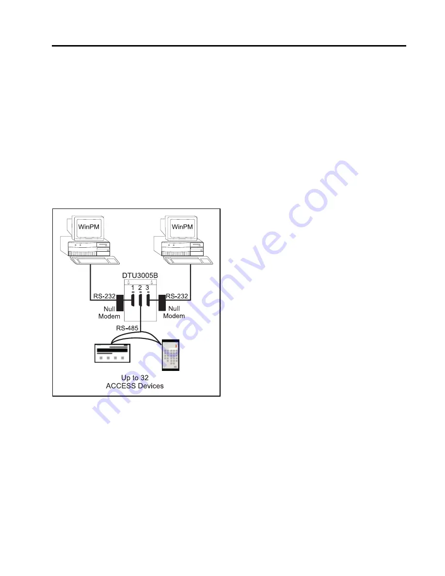
When configured as a SEAbus port expander, the
DTU3005 allows two computers running supervisory
software, such as WinPM, to connect to the same Sie-
mens SEAbus devices. Up to 32 devices may be
attached  to  port  2  of  the  DTU3005  by  an  RS-485  con-
nection. This configuration is shown below in

Figure 6.1

.

Figure 6.1 

Dual Passthrough Application

Once you have created or opened the project file,
select 

Edit

 from the main menu and the following

menu items appear:

Port 1 (Passthrough)

—allows you to configure the

communications settings for the supervisory
computer connected to port 1.

Port 2 (SEAbus Devices)

—allows you to configure

communications settings for SEAbus devices con-
nected to port 2.

Port 3 (Passthrough)

—allows you to configure the

communications settings for the supervisory
computer connected to port 3.

Содержание DTU3005-B

Страница 1: ...DTU3005 B Intelligent Data Transfer Device for Connection to PLCs and Modbus Networks Operator s Manual ...

Страница 2: ...ing with WinPM Can cause death serious injury or property damage See safety instruction contained herein Restrict use to qualified personnel The use of unauthorized parts in the repair of the equipment or tampering by unqualified personnel will result in dangerous conditions that can cause death serious injury or property damage IMPORTANT The information contained herein is general in nature and n...

Страница 3: ...8 Device Text Setup 7SJ600 Only 41 5 9 Global Command Registers 43 5 10 Device Diagnostic Registers 43 5 11 Device Command Registers 44 5 12 Saving the Project File 44 6 Creating Project Files SEAbus Port Expander45 6 1 Passthrough Setup Port 1 46 6 2 SEAbus Device Setup Port 2 48 6 3 Passthrough Setup Port 3 48 7 Transferring Project Files 49 7 1 Downloading Projects 50 7 2 Uploading Projects 51 ...

Страница 4: ...can coexist on the communications bus without having to support the newer features of the protocol Siemens continuously strives to ensure backward compatibility reliability and easy implementation of both protocols to meet current market communications requirements Siemens therefore reserves the right to make improvements including changes to specifications at any time without notice or obligation...

Страница 5: ...pported by the DTU3005 Appendix B lists the supported Siemens ACCESS devices and protective relays Figure 1 1 Panel Tec DTU3005 View Showing 3 Ports and Power Supply 1 2 Software Overview The DTU3005 Editor software is a MS DOS based pro gram for configuring the DTU3005 device It provides for uploading and downloading configurations via the computer s serial port You can edit and save configu rati...

Страница 6: ...e SEAbus devices at the same time as the PLC This is shown in Figure 1 3 An addi tional DTU3005 device can be attached to port 3 Up to 32 DTU3005 devices can be daisy chained together each connected to up to 32 Siemens devices This is shown in Figure 1 4 Figure 1 2 PLC to SEAbus Application Figure 1 3 PLC to SEAbus with Passthrough Figure 1 4 Daisy Chained DTU3005 Units 1 2 3 DTU3005B Up to 32 ACC...

Страница 7: ...ure 1 6 Up to 32 DTU3005B units can be daisy chained using a cable connected to port 1 of the three units Each DTU3005B device should have a different Modbus device number A daisy chained configuration is shown in Figure 1 7 Figure 1 5 Modbus Master to SEAbus Figure 1 6 Two Independent Modbus Master Devices to SEAbus 1 2 3 DTU3005B Up to 32 ACCESS Devices Acting as a Modbus RTU slave Data is reque...

Страница 8: ... SEAbus By using a Siemens Isolated Multi Drop Converter you can connect your Modbus Master device to four DTU3005 devices Each DTU3005 can connect to up to 32 Siemens ACCESS devices as well as be daisy chained to up to 32 additional DTU3005 devices An example configuration is shown below in Figure 1 8 Figure 1 8 Multi Drop Configuration ...

Страница 9: ...er The DTU3005 can be used as a SEAbus port expander for ACCESS devices allowing two personal comput ers running WinPM or other supervisory software to communicate with up to 32 ACCESS devices This configuration is shown below in Figure 1 9 Figure 1 9 SEAbus Port Expander ...

Страница 10: ...r B if that is your 3 diskette drive and then press Enter 2 At the A prompt type install and then press Enter The installation prompts you to select which Editor software to install as shown in the example screen below Type 1 and press Enter to install the SEAbus Device Editor or type 2 and press Enter to install the VDEW Device Editor 3 The program asks on which drive you want to install the Edit...

Страница 11: ...2 Installing the Software 7 Siemens Energy Automation Inc returns you to the DOS prompt as shown in the example screen below 7 If you are running Windows type exit to close the DOS window ...

Страница 12: ... mouse can be used to make menu selections highlight and select items in a dialog box and perform commands by clicking on dialog box buttons Keyboard equivalents to mouse actions are described in Table 3 1 below Informational messages are displayed on the bottom line of the screen to give you help with keyboard navigation Note To use a mouse in DOS be sure the mouse driver is loaded before startin...

Страница 13: ...to use Its operation is described in Chapter 8 3 3 Using the Project Menu When you first start the DTU3005 Editor software and no project file is loaded the following menu selections are available in the Project menu see example screen below Open allows you to open any saved project file New allows you to create a new project file Dos Shell allows you to switch to MS DOS with out closing the DTU30...

Страница 14: ...LC to control and or monitor up to 32 supported Siemens devices See Chapter 4 for configuring this project type Modbus Master to Devices allows a Mod bus speaking host system personal com puter running SCADA software or PLC to read and write registers in up to 32 supported Sie mens devices See Chapter 5 for configuring this project type SEAbus Port Expander allows two Siemens ACCESS supervisory co...

Страница 15: ...llows you to close a project file More than one project file can be open at any time View allows you to view a project informa tion screen which shows the project file name project file type the selections for each of the DTU3005 s ports and the number of devices Save allows you to save the current project file Save As allows you to save the project file under a different file name Switch To allow...

Страница 16: ... logic is required on the PLC to use the basic fea ture of this application which allows a limited amount of information to be transferred between the PLC and the devices Ladder logic programming is required to use the command block function The command block is used to send commands to the devices such as operating or releasing relays or resetting energy counters See Section 4 11 for information ...

Страница 17: ...r more information Device List allows you to indicate which SEAbus devices or Siemens protective relays are connected to port 2 and which PLC registers they are communicat ing with If the Device Protocol for port 2 is set to VDEW see Section 4 4 then two additional menu items are available Global Command Registers and Device Text to Values Table See Section 4 8 and Section 4 9 for instructions on ...

Страница 18: ...t uses a 2 wire connection To select the checkbox click on it with the mouse or with the 2 Wire RS422 or RS485 Communications selection highlighted press the spacebar An X will appear inside the brackets when it is selected Press the Tab or Right Arrow key to move to the next field without selecting this checkbox DTU Address Some PLC protocols require each device on the PLC net work to be assigned...

Страница 19: ...rt to return to the last previ ously saved configuration without saving any changes 4 4 Device Setup Port 2 One or more Siemens devices may be connected to port 2 You must have a PLC to Devices project file open to config ure port 2 using the instructions in this section Select Port 2 Devices from the Edit menu and the Port 2 configuration screen appears Device Protocol The Device Protocol indicat...

Страница 20: ...ort 3 Passthrough from the Edit menu and the Port 3 configuration screen appears The first option on the configuration screen allows you to choose passthrough to port 1 or port 2 Select the appropri ate port with the mouse or use the Up or Down Arrow keys to highlight the selection and press Enter The remaining configuration selections except for Intermes sage Time out are the same as those for po...

Страница 21: ... of the devices are visible on the screen at one time To see all the devices click on the scroll bar with the mouse or use the Up and Down Arrow and Page Up and Page Down keys The right side of the screen is used to configure the data register information for the selected device as shown in the example screen on the next page You can add or delete devices or change device configura tion by highlig...

Страница 22: ... below 4 With the Address field highlighted enter the device s address This number should be between 1 and 254 and match the number programmed into the device itself Press the Tab key twice to go to the Real Time Data Registers field 5 Highlight the File field and enter the file number This parameter is used only with Allen Bradley PLCs to specify the file number in the PLC that contains the reg i...

Страница 23: ...es Removing a Device To remove a device from the device list highlight the device on the left side of the screen and press Tab or Enter Then change the device type to Not In Use Additional Options for Data Registers The Device List screen has three additional options for working with a device s data registers Select Set Reg to place the data registers into contigu ous register numbers and minimize...

Страница 24: ...n the list and press Enter to see a list of available real time data These data items are identical to the standard data items listed in Appendix E Not all data items are visible on the screen at one time Use the mouse and the scroll bar or the Page Up and Page Down keys to view all of the data items ...

Страница 25: ... allo cate registers for those containing device data This does not apply to SEAbus devices for which the DTU3005 allo cates 16 registers regardless if they are used or not 4 7 2 Configuring Default Custom Device Registers by Device If you are configuring custom device registers for more than one device of a certain type you may configure the default custom registers from the Edit Menu Device Defa...

Страница 26: ...nu Use the scroll bar or the Page Up and Page Down keys to view all the entries Select Clear All to set all data words to Not Used Select Set to Base to restore the data words to the first 16 registers 64 for VDEW devices from the device s standard data regis ter list 4 Select Save to save your configuration or Revert to restore the last previously saved configuration for that device When you are ...

Страница 27: ...tem is only available for configuring the 7SJ600 relay It is used to convert status codes returned from select parameters in the 7SJ600 relay only to values in a format useful to the system connected to port 2 of the DTU3005 This affects the status readouts from the device s binary inputs signal and trip rated con tacts and the LEDs To edit this table select Device Text to Values Table from the Ed...

Страница 28: ...ng This Conversion Table Value Outputs S2 S1 T2 T1 Bits 15 4 3 2 1 0 1349 S1 2 T1 2 Open 0 0 0 0 0 0 1350 S1 2 T1 Open T2 Closed 2 0 0 0 1 0 1351 S1 2 T2 open T1 Closed 1 0 0 0 0 1 1352 S1 2 Open T1 2 Closed 3 0 0 0 1 1 1353 S1 T1 2 Open S2 Closed 8 0 1 0 0 0 1354 S1 T1 Open S2 T2 Closed 10 0 1 0 1 0 1355 S1 T2 Open S2 T1 Closed 9 0 1 0 0 1 1356 S1 Open S2 T1 2 Closed 11 0 1 0 1 1 1357 S2 T1 2 Ope...

Страница 29: ...troubleshoot problems with the devices and the communications network The format and content of the diagnostic registers are described in detail in Appendix F 1 To configure the device diagnostic registers select Diagnostics from the Edit menu The following screen displays 2 To enable the sending of diagnostic information to the PLC select the Do you want device diagnostics information sent to PLC...

Страница 30: ...hey are listed in the device list To use the command registers for a particular device the PLC program must do the following in order 1 First set the command word to 0 or 1 FFFF hexadec imal 2 Set the data word to the appropriate value 3 Set the command word to the appropriate value 4 After the command is set the PLC must wait for the DTU3005B unit to change the command word to either 0 to indicat...

Страница 31: ...ice information to the project file and then select Ok or press Esc to exit the device command registers screen If at any time you want to return to the last saved version of the device command registers select Revert without saving any changes 4 12 Saving the Project File Now you have completed configuring the DTU3005 for PLC to device communications Select Save from the Project menu and press En...

Страница 32: ...sually a SCADA system to control and monitor up to 32 SEAbus devices or Siemens pro tective relays In this application the DTU3005B acts as a slave and all communications with the Modbus Master are initiated by the master device itself The DTU3005B converts Modbus requests received into requests to access and control data on the Siemens devices Registers are assigned for each device in the Holding...

Страница 33: ...tic information to the Modbus Master Device Command Registers allows you to indi cate which PLC registers will be used for device commands Device Defaults allows you to set the default data registers for more than one device of a cer tain type e g set the defaults for all 4720 power meters or all S7 I O units The data registers can still be customized for each device as required See Section 5 7 2 ...

Страница 34: ...s project file open to configure port 1 using the instructions in this section Select Port 1 Modbus Master from the Edit menu and the Port 1 Modbus Master configura tion screen appears To select the protocol for the Modbus Master device connected to port 1 highlight Modbus Protocol and press Enter The Modbus Master Protocol selection menu appears ...

Страница 35: ... settings To move between the communications settings press the Tab or Enter keys To select a setting use the Up or Down Arrow key to move to the desired setting and press the spacebar to change your selection RTS Control Request to Send Control RTS Control selection is an option provided for modems or for Modbus Master devices that require RTS to be active only while the DTU is transmitting to th...

Страница 36: ...ESS communicating trip units relays power meters and other devices The VDEW protocol indicates connection to Sie mens protective relays using the VDEW protocol Note Not all Siemens devices are supported For a list of supported devices see Appendix B Other Configuration Information The remaining configuration selections are the same as those for port 1 Refer to Section 5 3 for instructions on these...

Страница 37: ...is section Select Port 3 Modbus Passthrough from the Edit menu and the Port 3 configuration screen appears The first option on the configuration screen allows you to choose connection to a second Modbus Master device or passthrough to port 2 Select the appropriate configuration with the mouse or use the Up or Down Arrow keys to highlight the selection and press the spacebar Modbus Master If you se...

Страница 38: ... is selected Press the Tab or Right Arrow key to move to the next field without selecting this checkbox Intermessage Time Out The DTU3005 uses the intermessage time out to determine when a complete message has been received on the passthrough port Once the first char acter of a message has been received if the amount of time specified by the intermessage time out passes with no additional characte...

Страница 39: ...ly 17 of the devices are visible on the screen at one time To see all the devices click on the scroll bar with the mouse or use the Up and Down Arrow and Page Up and Page Down keys The right side of the screen is used to configure the data register information for the selected device as shown in the example screen on the next page You can add or delete devices or change device configuration by hig...

Страница 40: ...umber should be between 1 and 254 and match the number programmed into the device itself Press the Tab key twice to go to the Real Time Data Registers field 5 Enter the beginning register number in the Real Time Data Registers field Refer to Appendix A for valid register numbers for your PLC application The DTU3005 Editor software supplies the last register number after you enter the first In the ...

Страница 41: ...onal Options for Data Registers The Device List screen has three additional options for working with a device s data registers Select Set Reg to place the data registers into contiguous register numbers and minimize the size to the data register block This option also sets the initial register number to 1 The Set All command performs the same function but allows you to set the initial register num...

Страница 42: ...ster on the list and press Enter to see a list of available real time data The data items are identical to the standard data items listed in Appendix E Not all data items are visible on the screen at one time Use the mouse and the scroll bar or the Page Up and Page Down keys to view all of the data items ...

Страница 43: ...Not Used and place them at the end of the list The DTU3005 will only allocate registers for those containing device data This does not apply to SEAbus devices for which the DTU3005 allocates 16 registers regardless if they are used or not 5 7 2 Configuring Default Custom Device Registers If you are configuring custom device registers for more than one device of a certain type you may con figure th...

Страница 44: ...e menu Use the scroll bar or the Page Up and Page Down keys to view all the entries Select Clear All to set all data words to Not Used Select Set to Base to restore the data words to the first 16 registers 64 for VDEW devices from the device s standard data register list 4 Select Save to save your configuration or Revert to restore the last previously saved configuration for that device When you a...

Страница 45: ... item is only available for configuring the 7SJ600 relay It is used to convert status codes returned from select parameters in the 7SJ600 relay only to values in a format useful to the system connected to port 2 of the DTU3005 This affects the status readouts from the device s binary inputs signal and trip rated contacts and the LEDs To edit this table select Device Text to Values Table from the E...

Страница 46: ...e Using This Conversion Table Value Outputs S2 S1 T2 T1 Bits 15 4 3 2 1 0 1349 S1 2 T1 2 Open 0 0 0 0 0 0 1350 S1 2 T1 Open T2 Closed 2 0 0 0 1 0 1351 S1 2 T2 open T1 Closed 1 0 0 0 0 1 1352 S1 2 Open T1 2 Closed 3 0 0 0 1 1 1353 S1 T1 2 Open S2 Closed 8 0 1 0 0 0 1354 S1 T1 Open S2 T2 Closed 10 0 1 0 1 0 1355 S1 T2 Open S2 T1 Closed 9 0 1 0 0 1 1356 S1 Open S2 T1 2 Closed 11 0 1 0 1 1 1357 S2 T1 ...

Страница 47: ...us Master to collect diagnostic information by reading the registers assigned here The information can be used to troubleshoot prob lems with the devices and the communications net work The format and content of the diagnostic registers are described in detail in Appendix F 1 To configure the device diagnostic registers select Diagnostics from the Edit menu The fol lowing screen displays 2 To enab...

Страница 48: ...he command registers follow these steps 1 Select Device Command Registers from the Edit menu The Device Command Registers screen appears 2 Enter the starting register address in the Modbus Registers field The DTU3005 Editor software will determine the proper number of registers for the number of devices entered in the device list and indicate the final register number The registers used are the ho...

Страница 49: ... software such as WinPM to connect to the same Sie mens SEAbus devices Up to 32 devices may be attached to port 2 of the DTU3005 by an RS 485 con nection This configuration is shown below in Figure 6 1 Figure 6 1 Dual Passthrough Application Once you have created or opened the project file select Edit from the main menu and the following menu items appear Port 1 Passthrough allows you to configure...

Страница 50: ...Port 1 Passthrough from the Edit menu and the Port 1 Passthrough configuration screen appears 2 Wire RS422 or RS485 Communications The 2 Wire RS422 or RS485 Communications selec tion box will only need to be checked if the communi cations with your supervisory computer is a 2 wire RS485 or RS422 interface An example of this is if you are using a RS 232 485 converter to extend the dis tance between...

Страница 51: ... only while the DTU is transmitting to the computer If RTS CTS is selected the DTU will activate RTS and wait until CTS is active before transmitting to the computer attached to port 1 If RTS Delay is selected the DTU will activate RTS and wait for the specified delay time to pass before transmitting When RTS Delay is selected the program displays an entry box for the RTS delay time Enter the time...

Страница 52: ...e time in milliseconds Saving Port 2 Configuration Information Once you have entered all the configuration informa tion select Save to save the configuration to the project file Then select Ok or press the Esc key to close the configuration screen If you have changed the configuration and have not saved it to the project file you will be prompted to either save or discard the changes Select Revert...

Страница 53: ...your PC to the DTU3005 Upload project from DTU3005 allows you to transfer upload the project file stored in the DTU3005 to the PC Verify allows you to verify a project file within your computer against the current project file stored in the DTU3005 unit Check Application in DTU3005 allows you to check what type of project file is loaded PLC to devices Modbus Master to devices or Passthrough and wh...

Страница 54: ...s in config uration mode Note To return the device to normal opera tion the DTU3005B unit must be pow ered off while the DIP switch settings are reset then the unit will be in normal operation mode when it is powered up Figure 7 2 DIP Switch Settings for Normal Operation and Configuration Modes Switch 4 is N A 7 1 Downloading Projects Select Download project to DTU3005 from the Trans fer menu and ...

Отзывы: