


22
AOP Operating Instructions – Issue 07/05
6SE6400-5AP00-0BB0
1.
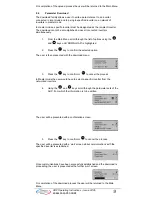
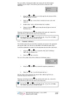
From the Main Menu scroll through the list of options using
the
and
keys until the required mode is highlighted.
2. Press
the key to confirm the selected option.
5.1 Local
Mode
In Local mode the AOP is normally mounted directly onto the inverter. Once
mounted it scans both the RS232 and the RS485 ports and establishes
communication with the first port that answers the AOPs interrogation.
Communications, as previously stated, are performed through the RS232 and
RS485 ports. Full operator control of the inverter is available with access to all
normal inverter and AOP internal parameters.
This mode is designed to work with only one inverter and is the default setting of
the AOP on initial power-up or after a reset has been performed.
5.2 Master
Mode
In Master mode the AOP can control up to 31 inverters connected in a multi-
drop arrangement.
Full operator control of each inverter is possible with access to all normal
inverter and AOP internal parameters.
Control of the inverters may be individual or by the broadcast method previously
described. In the broadcast mode it is possible only to start and stop the motor
directly simultaneously.
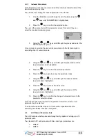
5.3 Internal
Mode
In Internal mode the user has access to the AOP’s own parameter sets, which
are store within the AOP’s hardware. No access is given, in this mode, to the
parameter sets held within the inverter.
5.4 Slave
Mode
In this mode the AOP is configured to communicate with a PC utilizing the AOP
Desk Mounting Kit and communications software, such as, Starter or
DriveMonitor. The AOP in this configuration acts as a slave to the PC, allowing
the upread of parameter sets or the AOPs internal parameter set to be accessed
as a USS address, numbered 1 to 10.
5.5 PC
Mode
In PC mode the AOP is configured to act as an RS232/485 converter when used
with a Panel Mount Kit, enabling an attached PC, with suitable software to
control a network of inverters.
The only function that can be modified in this mode of operation is the
communications baud rate.
See notes on Network Set-up for PMK configuration on page 5.
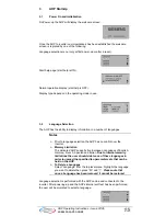
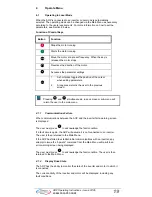
6 Parameter
Access
6.1
Standard Level Parameters
The AOP has been designed to allow the editing of individual parameters within
the inverter.
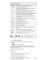
Access levels control the access to parameters. Each level allowing the user to
use a more sophisticated control technique for the applications.