background image

3/8

Siemens

Electromotoric actuators

CA1N4895en

Smart Infrastructure

2019-10-02

When the AC / DC 24 V supply is applied for the first time, the actuators calibrate
themselves independent of the control signal. In this process, the actuator drives the
valve to the mechanical end stops and stores the associated positions permanently in the
form of electronic values. The positioning signal is only active on completion of this
calibration process. Calibration takes about 60 seconds.
The SSC61.5 only performs self-calibration when the charging process is completed.

If the calibrated actuator is used with
some other valve (e.g. a replacement
valve), it must be recalibrated.

1.  Unscrew screws
2.  Remove cover
3.  Connect the 2 contacts behind the

slot for about 1 second.

The calibration can only be made correctly if the actuator is fitted to a valve (refer to
«Equipment combinations», page 2).

·

Plastic cover

·

Position indication

·

Locking-proof, maintenance-free gear train

·

Manual adjustment with rotary knob

·

Reduced power consumption in the holding positions

·

Load-dependent switch-off in the event of overload and in stroke end positions

·

Parallel operation of 10 SSC.. possible, provided the controllers’ output is sufficient

Accessories

Type ASK30

Mounting kit for Landis & Gyr valves VVG45…, VXG45… and
X3i..

Notes

The actuators must be electrically connected in accordance with local regulations (refer
to «Connection diagrams», page 7).

Regulations and requirements to ensure the safety of people and property must
be observed at all times!

The permissible temperatures must be observed (refer to «Technical data», page 5).

Mounting Instructions 74 319 0260 0 are enclosed with each pack.
Assembly is made with the coupling nut; no tools or adjustments are required. The
actuators should be installed so that they are initially in position 0 (also refer to «Manual
override», page 4).

Self-calibration

SSC61 and SSC61.5

Recalibration

Features and benefits

Mounting kit

Engineering

  Caution

Mounting

Содержание Acvatix SSC31

Страница 1: ...safe function Nominal force 300 N Automatic identification of valve stroke Direct mounting with coupling nut no tools required Cable connection via screw terminals Manual override with indication of position and direction of travel Parallel connection of multiple actuators Use For operation of Siemens valves of the V P45 range for water side control of hot and cooling water in heating ventilation ...

Страница 2: ... a stroke which is transmitted to the valve stem Voltage at Y1 Actuator stem extends valve opens Voltage at Y2 Actuator stem retracts valve closes No voltage at Y1 or Y2 Actuator maintains the current position The valve opens closes in proportion to the control signal at Y At DC 0 V the valve is fully closed A AB When power supply is removed the actuator maintains its current position When first c...

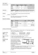
Страница 3: ...2 Plastic cover Position indication Locking proof maintenance free gear train Manual adjustment with rotary knob Reduced power consumption in the holding positions Load dependent switch off in the event of overload and in stroke end positions Parallel operation of 10 SSC possible provided the controllers output is sufficient Accessories Type ASK30 Mounting kit for Landis Gyr valves VVG45 VXG45 and...

Страница 4: ...priority in determining the position To retain the manually set position unplug the connecting cable or switch off the rated voltage and the control signal Due to the reset function the SSC61 5 will first travel to position 0 and can then be driven manually to the required position B A B Y Y2 Y Y1 A 4895Z04 A 4895Z05 0 1 Position indicator in position 1 Valve OPEN B 4895Z06 0 1 Position indicator ...

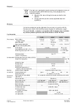
Страница 5: ...use for incoming cable fast 2 A Control Control signal 3 position DC 0 10 V Input impedance for DC 0 10 V 100 kOhm Positioning accuracy for DC 0 10 V 2 of nominal stroke Parallel operation number of actuators 2 max 10 Functional data Running time for 5 5 mm stroke at 50 Hz 150 s 30 s Capacitor charging time max 180 s Fail safe run time 30 s Nominal stroke 5 5 mm Nominal force 300 N Permissible tem...

Страница 6: ...180 s during power up capacitor will be charged for automatic reset 2 Provided the controllers output is sufficient 3 The documents can be downloaded from http siemens com bt download General ambient conditions Operation EN 60721 3 3 Transport EN 60721 3 2 Storage EN 60721 3 1 Environmental conditions class 3K3 class 2K3 class 1K3 Temperature 5 50 C 25 70 C 25 70 C Humidity non condensing 5 95 r h...

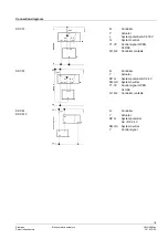
Страница 7: ...al Y1 Y2 Control signal OPEN CLOSE Q1 Q2 Controller contacts 4864A02 Y1 G G0 SP SN AC 24 V G Y2 Y1 Y2 N Q1 Q2 2AF Y N Controller Y Actuator SP G System potential AC 24 V SN G0 System neutral Y1 Y2 Control signal OPEN CLOSE Q1 Q2 Controller contacts 4864A03 Y N Y G0 G Y G0 SP SN AC 24 V DC 24 V G 2AF N Controller Y Actuator SP G System potential AC DC 24 V SN G0 System neutral Y Control signal SSC3...

Страница 8: ... reference Valid from Rev No Type reference Valid from Rev No SSC31 J SSC61 J SSC81 J SSC61 5 J Issued by Siemens Switzerland Ltd Smart Infrastructure Global Headquarters Theilerstrasse 1a 6300 Zug Switzerland Tel 41 58 724 24 24 www siemens com buildingtechnologies Siemens Switzerland Ltd 2004 2019 Technical specifications and availability subject to change without notice ...

Отзывы: