background image

4/8

Siemens

Electromotoric actuators

CA1N4895en

Smart Infrastructure

2019-10-02

90°

43

6

2Z

01

90°

When commissioning the system, check wiring and the functions of the actuator.

Before testing the functioning of the SSC.., always check to ensure that the
actuator concerned is mounted on a valve (refer to «Equipment combinations»,
page 2)
.

Calibrating the SSC61 or SSC61.5 without a valve connected causes the actuator to
lock in position 1. To recalibrate (after mounting on a valve), disconnect power and
reset the stroke manually from position 1 to 0 (refer to «Recalibration», page 3).

The rotary knob can be used to drive the actuator into any position between 0 and 1. If a
control signal from the controller is present, this will take priority in determining the
position.

To retain the manually set position, unplug the connecting cable or switch off the rated
voltage and the control signal. Due to the reset function, the SSC61.5 will first travel to
position 0 and can then be driven manually to the required position.

B

A

B

(Y, Y2)

(Y, Y1)

 A

48

9

5Z

0

4

A

48

95Z

05

0

1

Position indicator in

position 1:

Valve OPEN

B

48

95

Z

06

0

1

Position indicator in

position 0:

Valve CLOSED

After manual override with the rotary knob the positioning signal and the stroke
synchronize autonomously, if the positioning signal is once > 9.7 V or < 0.3 V.

When servicing the actuator:

·

Switch off power

·

If necessary, disconnect the terminals

·

The actuator must only be commissioned with a correctly mounted valve in place!

The SSC.. actuators cannot be repaired. They must be replaced as a complete unit.

Orientation

Commissioning

  Caution

Operation

Note

Manual override

Note SSC61…

Maintenance

Repair

Содержание Acvatix SSC31

Страница 1: ...safe function Nominal force 300 N Automatic identification of valve stroke Direct mounting with coupling nut no tools required Cable connection via screw terminals Manual override with indication of position and direction of travel Parallel connection of multiple actuators Use For operation of Siemens valves of the V P45 range for water side control of hot and cooling water in heating ventilation ...

Страница 2: ... a stroke which is transmitted to the valve stem Voltage at Y1 Actuator stem extends valve opens Voltage at Y2 Actuator stem retracts valve closes No voltage at Y1 or Y2 Actuator maintains the current position The valve opens closes in proportion to the control signal at Y At DC 0 V the valve is fully closed A AB When power supply is removed the actuator maintains its current position When first c...

Страница 3: ...2 Plastic cover Position indication Locking proof maintenance free gear train Manual adjustment with rotary knob Reduced power consumption in the holding positions Load dependent switch off in the event of overload and in stroke end positions Parallel operation of 10 SSC possible provided the controllers output is sufficient Accessories Type ASK30 Mounting kit for Landis Gyr valves VVG45 VXG45 and...

Страница 4: ...priority in determining the position To retain the manually set position unplug the connecting cable or switch off the rated voltage and the control signal Due to the reset function the SSC61 5 will first travel to position 0 and can then be driven manually to the required position B A B Y Y2 Y Y1 A 4895Z04 A 4895Z05 0 1 Position indicator in position 1 Valve OPEN B 4895Z06 0 1 Position indicator ...

Страница 5: ...use for incoming cable fast 2 A Control Control signal 3 position DC 0 10 V Input impedance for DC 0 10 V 100 kOhm Positioning accuracy for DC 0 10 V 2 of nominal stroke Parallel operation number of actuators 2 max 10 Functional data Running time for 5 5 mm stroke at 50 Hz 150 s 30 s Capacitor charging time max 180 s Fail safe run time 30 s Nominal stroke 5 5 mm Nominal force 300 N Permissible tem...

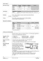
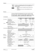
Страница 6: ...180 s during power up capacitor will be charged for automatic reset 2 Provided the controllers output is sufficient 3 The documents can be downloaded from http siemens com bt download General ambient conditions Operation EN 60721 3 3 Transport EN 60721 3 2 Storage EN 60721 3 1 Environmental conditions class 3K3 class 2K3 class 1K3 Temperature 5 50 C 25 70 C 25 70 C Humidity non condensing 5 95 r h...

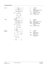
Страница 7: ...al Y1 Y2 Control signal OPEN CLOSE Q1 Q2 Controller contacts 4864A02 Y1 G G0 SP SN AC 24 V G Y2 Y1 Y2 N Q1 Q2 2AF Y N Controller Y Actuator SP G System potential AC 24 V SN G0 System neutral Y1 Y2 Control signal OPEN CLOSE Q1 Q2 Controller contacts 4864A03 Y N Y G0 G Y G0 SP SN AC 24 V DC 24 V G 2AF N Controller Y Actuator SP G System potential AC DC 24 V SN G0 System neutral Y Control signal SSC3...

Страница 8: ... reference Valid from Rev No Type reference Valid from Rev No SSC31 J SSC61 J SSC81 J SSC61 5 J Issued by Siemens Switzerland Ltd Smart Infrastructure Global Headquarters Theilerstrasse 1a 6300 Zug Switzerland Tel 41 58 724 24 24 www siemens com buildingtechnologies Siemens Switzerland Ltd 2004 2019 Technical specifications and availability subject to change without notice ...

Отзывы: