3 / 14
Siemens
Electromotive actuators for combi valves
CE1N4833en
Building Technologies
2017-11-15
Technology/Mechanical design
1
4833Z01
1
2
3
5
7
6
4
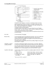
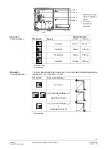
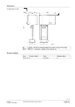
1 Status and acting direction
indication (LED)
2 Housing cover
3 Entry points for cable glands
4 Manual adjuster
5 Indication of upper end
position
6 Valve stem coupling
7 Indication of lower end
position
8 Valve neck coupling
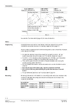
The actuator can be operated as a 3-position or modulating actuator in two acting
directions depending on the type of connection. It is suitable for both combi valves
VPF.. with 20 mm stroke as well as for valves with a 40 mm and 43 mm stroke. The
stroke is calibrated automatically during initialization.
The actuator includes a position feedback.
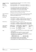
The actuator travels to the end position in the event of power loss, see "
", page 5. Up to 45 seconds pass until the actuator is available again following
a restart or start after the fail-safe function is triggered.
The positioning time (40 to 240 seconds) and the flow characteristic (lin/log) can be set
via the DIL switches.
The manual adjuster is disengaged.
The manual adjuster allows for manually setting the position. The motor is switched off
when the manual adjuster is engaged. The fail-safe function (spring return) is
reactivated after the manual adjuster is disengaged, and the actuator travels again to
the set position without calibration.
The actuator remains in this position without active operating voltage for as long as the
manual adjustor is engaged.
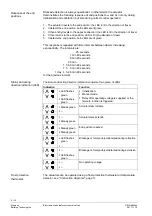
The actuator independently calibrates itself for each type of connection. Initialization
occurs as soon as operating voltage is supplied for the first time and the waiting period
ends. The actuator travels to the lower stop of the combi valve, thus enabling automatic
coupling with the valve stem. It then travels to the upper stop, records and stores it.
Recalibration can be manually triggered any time, see "
", page 5.
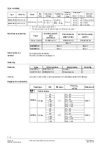
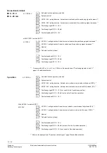
The combi valve can travel to any position by supplying voltage to terminal G1 or G2 as
well as L1
1)
or L2
1)
.
∂
Voltage on G2, L2:
Actuator stem retracts, combi valve opens.
∂
Voltage on G1, L1:
Actuator stem extends, combi valve closes.
∂
No voltage on G1 and G2:
Actuator stem stays at the applicable
or L1 and L2:
position.
1)
When using the AC 230 V module ASP1.1.
Auto mode
Manual mode
Initialization, automatic
coupling, calibration
3-position control signal


