4 / 14
Siemens
Electromotive actuators for combi valves
CE1N4833en
Building Technologies
2017-11-15
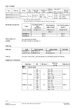
The acting direction of the stroke direction can be reversed by exchanging
connections G1 and G2 or L1 and L2.
Positioning signal OPEN on G2, L2. Positioning signal CLOSED on G1, L1.
Positioning signal OPEN on G1, L1. Positioning signal CLOSED on G2, L2.
∂
Do not use connection Yu (DC 0-10 V) and Yi (DC 4-20 mA).
∂
Positioning times can be selected, see "Positioning times“, page 7".
∂
Valve characteristic curves "lin" or "log" cannot be selected.
∂
Position feedback U is activated after initialization/calibration.
Electronic motor shutdown is triggered in the end positions (valve stop or upon
reaching maximum stroke) or by overload (no end switch).
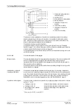
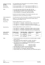
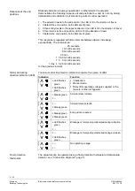
The combi valve can be driven to any position by connecting a continuous positioning
signal Yu or Yi. The acting direction can be reserved (direct/reverse acting) by
connecting operating voltage to G1 or G2:
Operating voltage AC/DC 24 V on G1 or AC 230 V on L1
∂
Pos. signal to Yu, Yi increasing: Actuator stem retracts, combi valve opens.
∂
Pos. signal to Yu, Yi decreasing: Actuator stem extends, valve closes.
∂
Pos. signal to Yu, Yi continuous: Actuator stem remains in the respective pos.
Operating voltage AC/DC 24 V on G2 or AC 230 V on L2
∂
Pos. signal to Yu, Yi increasing: Actuator stem extends, combi valve closes.
∂
Pos. signal to Yu, Yi decreasing: Actuator stem retracts, combi valve opens.
∂
Pos. signal to Yu, Yi continuous: Actuator stem remains in the respective pos.
Position signal
Operating voltage
Actuator stem
Combi valve
Yu, Yi increasing
G1 to AC/DC 24 V
L1 to AC 230 V
Retracts
Opens
Yu, Yi increasing
G2 to AC/DC 24 V
L2 to AC 230 V
Extends
Closes
∂
The input with the higher value has priority when a positioning signal is available
at both Yu and Yi.
∂
When using the AC 230 V module ASP1.1, the SQV..P can also be
operated with a DC 0…10 V or DC 4…20 mA positioning signal.
∂
The actuator travels to the applicable end position depending on the selected
acting direction if Yu or Yi are interrupted
:
Operating voltage to G1 or L1
Actuator stem extends.
Operating voltage to G2 or L2
Actuator stem retracts.
∂
Positioning times can be selected, see "Positioning times“, page 7".
∂
Valve characteristic curves "lin" or "log" can be selected.
∂
Position feedback U is activated after initialization/calibration.
∂
Parallel operation with up to 5 actuators possible, see "Technical data", page 10.
Changeover of acting
direction
Direct acting
Reverse acting
Notes
Positioning signals Yu
and Yi
DC 0-10 V (Yu)
DC4-20 mA (Yi)
Direct acting
Reverse acting
Acting direction
Direct acting
Reverse acting
Notes


