8 / 14
Siemens
Electromotive actuators for combi valves
CE1N4833en
Building Technologies
2017-11-15
Accessories
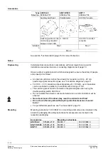
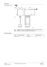
Type
Stock no.
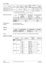
ASC10.42
S55845-Z137
ASZ7.6/1000
S55845-Z136
ASP1.1
S55845-Z138
Auxiliary switch pair
Potentiometer
AC 230 V module
4833Z18
4833Z17
4833Z16
Switching points can be
continuously adjusted
between 0 and 100%
0…1000 Ω
AC 230 V to AC 24 V
converter
Installatio
n
Max. 1
Max. 1
Max. 2
See section "Technical data" (page 10) for more information.
Notes
Install electrical connections in accordance with local regulations on electric
installations as well as internal or connecting diagrams as of page 10.
Observe safety regulations and restrictions designed to ensure the safety of people
and property at all times!
∂
An internal controller controls the actuator for 3-position or DC 4…20 mA
positioning signal connection types, see "Connection diagrams", page 11.
∂
For DC 0…10 V connections (input impedance R
i
= 100 kΩ), up to 5 actuators
can be controlled in parallel by a controller with a rating of 1 mA.
∂
The switching points must be entered on the plant diagram when using the
double auxiliary switch ASC10.42.
∂
Do not insulate the actuator console and valve stem, as air circulation must be
ensured.
∂
Non-observance of the above may result in accidents and fires!
∂
Do not touch the hot parts without prior protective measures to avoid
burns!
∂
For permitted temperatures, see "Technical data", page 10.
Mounting instructions 74 319 0821 0 on mounting combi valves are included in the
actuator's packaging. Mounting instructions for accessories are located in the
respective packaging.
Accessories
Mounting instructions
ASC10.42
S55845-Z137 M4833.1
74 319 0860 0
ASZ7.6/1000
S55845-Z136 M4833.2
74 319 0861 0
ASP1.1
S55845-Z138
M4833.3
74 319 0862 0
Engineering
Mounting


