background image

5 / 14

Siemens

Electromotive actuators for combi valves

CE1N4833en

Building Technologies

2017-11-15

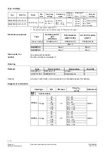
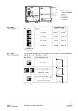
Position feedback U (DC 0…10 V) is always proportional to stroke H for the actuator. It
is also active when using the AC 230 V module ASP1.1.

DIL switch

Flow characteristics

Position feedback U

lin = linear

1)

log = equal percentage, n

gl

 = 3

(logarithmic normal)

log = equal percentage, n

gl

 = 3

(exponential normal)

1)

 Factory setting

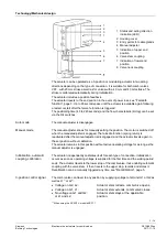
The actuator travels to the applicable end position (the stem retracts or extends
depending on the model) using the preloaded spring if operating voltage to terminal G
or L is lost or shut down. In this case, the actuator's control function is locked for 45
seconds (both LEDs are green) to reach the end position at any rate. There is no
recalibration. The reset positioning speed ensures that no pressure surges occur in the
piping.

SQV91P30  Actuator stem retracted

Combi valve opened (V = 100%).

SQV91P40  Actuator stem extended

Combi valve closed (V = 0%).

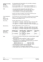
Recalibration can be manually triggered any time.

1.  Operating voltage is supplied.
2.  Engage and disengage the manual adjuster twice within 4 seconds.
3.  Both LEDs flash green.
4.  Recalibration is successful when both LEDs are lit green.
5.  Return to normal control function.

  Position feedback U is inactive or corresponds to value "0".

  The shortest possible runtime is initialized.

  Recalibration is valid only after the entire process is completed.

  Additional engaging the manual adjuster interrupts the process.

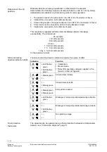
The valve actuator indicates detected blockage by setting the feedback signal to 0 V
after ca. 90 seconds. The actuator, however, tries to overcome the blockage during this
period. Normal control function is reactivated if the blockage is overcome and position
feedback U is once again available.

Position feedback U

Fail-safe function

End position

Recalibration

Notes

Blockade detection

Содержание ACVATIX SQV..P Series

Страница 1: ...uster position and status indication LED Selectable positioning times 40 240 seconds Fail safe function combi valve open closed Selection of acting direction Optional functional extension Auxiliary switch potentiometer and AC 230 V module Direct mounting on combi valves UL approved Use Electromotive actuators to operate Siemens combi valves for type series VPF43 and VPF53 with 20 40 43 mm stroke a...

Страница 2: ... Auxiliary switch pair ASC10 42 Potentiometer ASZ7 6 1000 AC 230 V module ASP1 1 Stock number S55845 Z137 S55845 Z136 S55845 Z138 Max 2 SQV91P30 Max 1 Max 1 SQV91P40 Max 1 Max 1 No spare parts available Revision numbers see page 13 Ordering Type Stock number Designation Quantity SQV91P40 S55150 A131 Actuator 1 ASZ7 6 1000 S55845 Z136 Potentiometer 1 Actuator combi valve and accessories are individ...

Страница 3: ... disengaged The manual adjuster allows for manually setting the position The motor is switched off when the manual adjuster is engaged The fail safe function spring return is reactivated after the manual adjuster is disengaged and the actuator travels again to the set position without calibration The actuator remains in this position without active operating voltage for as long as the manual adjus...

Страница 4: ...ve pos Operating voltage AC DC 24 V on G2 or AC 230 V on L2 Pos signal to Yu Yi increasing Actuator stem extends combi valve closes Pos signal to Yu Yi decreasing Actuator stem retracts combi valve opens Pos signal to Yu Yi continuous Actuator stem remains in the respective pos Position signal Operating voltage Actuator stem Combi valve Yu Yi increasing G1 to AC DC 24 V L1 to AC 230 V Retracts Ope...

Страница 5: ...es occur in the piping SQV91P30 Actuator stem retracted Combi valve opened V 100 SQV91P40 Actuator stem extended Combi valve closed V 0 Recalibration can be manually triggered any time 1 Operating voltage is supplied 2 Engage and disengage the manual adjuster twice within 4 seconds 3 Both LEDs flash green 4 Recalibration is successful when both LEDs are lit green 5 Return to normal control functio...

Страница 6: ...are 25 seconds 1 min 40 seconds 6 min 40 seconds 26 min 1 h 46 min 40 seconds 7 h 6 min 40 seconds 1 day 4 h 26 min 40 seconds for the previous interval The status and acting direction indication consists of two green lit LEDs Indication Function 4833Z08 ƒ LED flashes green ƒ LED flashes green ƒ Initialization ƒ Manual mode ƒ Delay after operating voltage is supplied or the fail safe function is t...

Страница 7: ...2 3 4 ON 4833Z02c 4 5 sec mm 90 sec 180 sec 1 2 3 4 ON 4833Z02d 6 sec mm 120 sec 240 sec 1 Tolerance 1 sec 2 Factory setting The flow characteristics can be used only for connections with constant positioning signals DC 0 10 V and DC 4 20 mA DIL switch Flow characteristics 1 2 3 4 ON 4833Z03a lin linear 1 1 2 3 4 ON 4833Z03b 1 2 3 4 ON 4833Z03c log equal percentage ngl 3 logarithmic normal 1 2 3 4...

Страница 8: ...sition or DC 4 20 mA positioning signal connection types see Connection diagrams page 11 For DC 0 10 V connections input impedance Ri 100 kΩ up to 5 actuators can be controlled in parallel by a controller with a rating of 1 mA The switching points must be entered on the plant diagram when using the double auxiliary switch ASC10 42 Do not insulate the actuator console and valve stem as air circulat...

Страница 9: ...missioning the valve Trigger stroke calibration after servicing There are no spare parts available the entire actuator must be replaced Removing the spring on the actuator is prohibited due to the high risk of injury Disposal The device is considered an electronics device for disposal in terms of European Directive 2012 19 EU and may not be disposed of as domestic garbage Dispose of the device thr...

Страница 10: ...c 3 Position feedback Position feedback U DC 0 10 V Load impedance 2 5 kΩ res Load Max 4 mA Connecting cable Wire cross sectional areas 0 75 1 5 mm 2 AWG 20 16 4 Cable entry 2 entry points M20 x 1 1 entry points M16 x 1 5 Degree of protection Housing from vertical to horizontal IP 66 as per EN 60529 Insulation class As per EN 60730 AC DC 24 V III With ASP1 1 AC 230 V module II Environmental condit...

Страница 11: ...e AC 230 V module ASP1 1 Voltage AC 230 V 5 Power consumption 22 VA 1 Factory setting 2 Control function is locked for 45 seconds 3 At 23 C ambient temperature and 1100 N nominal load 4 AWG American wire gauge 5 The documents can be downloaded from http siemens com bt download Connection diagrams DC 0 10 V DC 4 20 mA 3 position Y1 actuator N1 controller F1 frost protection thermostat DC 0 10 V DC ...

Страница 12: ...fer to the description at Positioning signals Yu and Yi page 4 for additional details AC DC 24 V Fail safe function system potential System neutral AC DC 24 V acting direction Actuator stem retracts combi valves fully open 100 1 AC DC 24 V acting direction Actuator stem extends combi valves fully closed 0 1 Positioning signal DC 0 10 V not used for the 3 position operation Positioning signal DC 4 ...

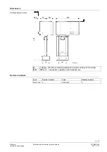
Страница 13: ...ilding Technologies 2017 11 15 Dimensions 4833Z19 64 289 44 100 mm Minimum mounting distance to wall or ceiling for mounting connection operation maintenance etc 200 mm Revision numbers Type Revision number Type Revision number SQV91P30 A SQV91P40 A All dimensions in mm ...

Страница 14: ...11 15 Issued by Siemens Switzerland Ltd Building Technologies Division International Headquarters Gubelstrasse 22 6301 Zug Switzerland Tel 41 58 724 24 24 www siemens com buildingtechnologies Siemens Switzerland Ltd 2011 Technical specifications and availability subject to change without notice ...

Отзывы: