


23 / 92
Siemens
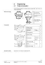
Actuators SAX.., SAY.., SAV.., SAL.. for valves
CE1P4040en
Building Technologies
Engineering
2018-12-05
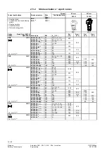
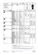
2.9.2
Permissible cable lengths and wire cross-sectional
areas
Cable lengths and wire cross-sectional areas depend on the following criteria of the
actuators:
·
Current draw
·
Permissible voltage drop across the power supply lines
The control accuracy of the modulating actuators can be improved by using 4-wire
connections, thus ensuring that voltage drops on G0 will not distort the positioning
signal.
When determining the cable length and the wire cross-sectional area, adherence to
the permissible operating voltage tolerance at the actuator is of importance, in
addition to the permissible voltage drop across the operating voltage and signal
lines (see table below).
Product no.
Operating voltage
Terminal
Max. permissible
voltage drop
SA..31..
AC 230 V
N, Y1, Y2
2% each (total of 4%)
SA..61..
AC/DC 24 V
G0, G
G0, Y, U
4% each (total of 8%)
1% each (at DC 0…10 V)
SA..81..
G, Y1, Y2
4% each (total of 8%)
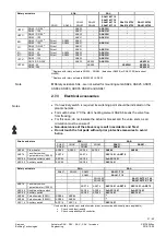
The following criteria must be considered:
·
With modulating control, the permissible positioning signal error must not exceed
1%, the reason being the voltage drop on the G0 wire.
·
The voltage drop, caused by charging current peaks in the actuator’s DC circuit,
must not exceed 2 Vpp.
·
If the G0 line is not correctly sized, load changes of the actuator due to changes
of the DC voltage drop might lead to self-oscillations.
·
The operating voltage drop at AC/DC 24 V may be a maximum of 8% (4% above
the G0 wire).
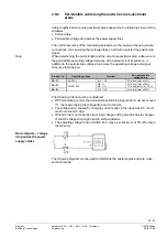
The following diagram can be used to determine the cable lengths and wire cross-
sectional areas.
Note
Basic diagram
−
voltage
drop across the power
supply cables