INTRODUCTION
_________________________________________________________________________________________________________
2-4
COM-00-21-03 OCTOBER 2021
Version No.: A
2.3
Electrical Design
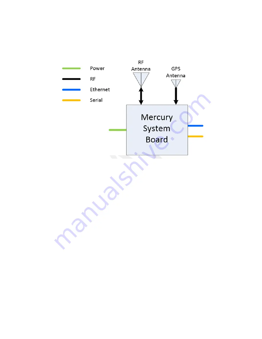
A block diagram of the Airlink Mercury radio is shown in Figure 2-3.
Figure 2-3 Mercury Radio Block Diagram
2.4
Functional Theory of Operation
Airlink can use Time Division Duplexing (TDD), meaning the downlink and uplink
communication uses the same frequency, but at different times or Half Duplex Frequency
Division Duplexing (FDD) where the downlink and the uplink use different frequencies (still at
different times - simultaneous transmission is not supported currently). Time separation
between the downlink and uplink messages is done with TDD framing. A TDD radio is
constantly toggling between transmit and receive states. The Base Station transmits during the
downlink subframe (DLSF) and receives during the uplink subframe (ULSF) while the remote
station transmits during the ULSF and receives during the DLSF.
The Airlink TDD radio uses a fast-switching power amplifier (PA) and transmit/receive (TX/RX)
switch. The PA gate voltage is used to switch the PA in less than 2 µs between transmit and
receive states. The TX/RX switch switches the antenna to the PA during the transmit phase and
to the low noise amplifier (LNA) during the receive phase. The PA does not transmit during the
receive state and the PA is maintained in the off state during the receive phase if transmission is
not needed to minimize power consumption.
To avoid self-interference, the TDD frame structure (i.e. the duration of the DLSF, ULSF, and
the total gap), is identical across the entire system. Additionally, the beginning of the TDD frame
is synchronized to a 1 pulse per second (PPS) generated by a GPS receiver. All Base Stations
in the system transmit at the same time. A Base Station (BS) and Remote Station (RS) never
transmit at the same time, so they never interfere with each other.


