=USNJVOTPKV=G=fkpq^iiqflk=fkpqor`qflkp=Ua^=G=oÉîáëáçå=MP
33
fåëí~ää~íáçå
!
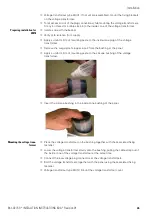
Undo the locking cap of the maintenance valve
s
for the completely closed busbar
run.
!
Connect the vacuum pump to the valve of the busbar run
s
. Use short tubes with
the largest inside diameter possible.
!
Evacuate the housings down to a pressure of less than 2 kPa. Manometer indication:
-100 kPa. Measure the pressure with the vacuum pump locked.
!
Depending on the inside diameter and length of the vacuum pump tube, let the
pump operate for another 5 to 15 minutes.
!
Remove the pump tube. The maintenance valve closes automatically.
Filling the busbar run with
an SF
6
-gas cyclinder
!
Determine the filling pressure required according to the rating plate and the data
given in Section "Technical data" (see "Description" 14.4, Page 22). The pressure
depends on the gas temperature.
!
Connect the SF
6
-gas cylinder to the maintenance valve of the evacuated busbar run.
!
Fill SF
6
into the busbar run until the necessary pressure is reached. Check the filling
pressure on the pressure indicator of the busbar run and on the pressure indicator of
the gas filling equipment.
!
Remove the connecting tube of the gas cylinder from the maintenance valve. The
maintenance valve closes automatically.
!
Refit the locking cap of the maintenance valve.
Fig. 23: Pressure indicators and maintenance valves at
the switchgear front
a
Pressure indicator for busbar housings
(number according to design of busbar sys-
tem)
s
Gas filling socket for busbar housings (num-
ber according to design of busbar system)
d
Pressure indicator for circuit-breaker hou-
sing
f
Gas filling socket for circuit-breaker housing


