background image

7XV5461-0Bx00

English

C53000-B1174-C173-5

63

Reach 

100 km

:

– Path attenuation

With singlemode fibre, the light of the
wave length 

λ

 = 1550 nm is anticipated with

an optical signal attenuation of 0.22 dB/km.

– Optical wave length

λ

 = 1550 nm 

When using the 60-km device model for transmission links < 50 km, two attenuators must
be connected to the end of the remote connection (see chapters Connection Notes and
Installation Notes).

Reach 

170 km

:

– Path attenuation

With singlemode fibre, the light of the
wave length 

λ

 = 1550 nm is anticipated with

an optical signal attenuation of 0.22 dB/km.

– Optical wave length

λ

 = 1550 nm 

When using two 170 km device variants for transmission distances that are less than
100 km, both delivered attenuators must be connect to the end of the remote connection (Rx
and Tx) on one of the devices (see chapters Connection Notes and Installation Notes).

Note:

One attenuator is delivered pro 170 km device variant.

min.

max.

Transmitting power coupled in singlemode fibre

-5.0 dBm

avg

0 dBm

avg

Receiver sensitivity

-34 dBm

avg

-34.5 dBm

avg

Optical Power Budget

29 dB

min.

max.

Transmitting power coupled in singlemode fibre

+1 dBm

avg

+5 dBm

avg

Receiver sensitivity

-45 dBm

avg

-

Optical Power Budget

43 dB

Caution! 

For transmission links < 100 km, connecting the two attenuators to the
end of remote connection is required as the optical receivers may be
damaged otherwise.

Содержание 7XV5461-0B 00 Series

Страница 1: ...yright Siemens AG 2008 Handbuch Manual Bestell Nr Order No C53000 B1174 C173 5 Hinweise für den Einsatz Deutsch Seite 3 Weitverkehr Fibre Optic Repeater Directions for Use English page 39 Wide Area Fibre Optic Repeater ...

Страница 2: ...r Siemens AG Die übrigen Bezeichnungen in diesem Handbuch können Marken sein deren Benutzung durch Dritte für deren Zwecke die Rechte der Inhaber verletzen können Liability Statement We have checked the text of this manual against the hardware and software described Exclusions and deviations cannot be ruled out we accept no liability for lack of total agreement The information in this manual is ch...

Страница 3: ...Warnungen 4 Aus und Einpacken des Gerätes 6 Lagerung und Transport 6 Verwendung 7 Merkmale 10 Funktion 11 Schnittstellen und Anschlüsse 12 Anschlusshinweise 14 Montage 18 Inbetriebsetzung 20 Technische Daten 22 Maßbilder bis Hardwareausgabestand CC 36 Maßbilder ab Hardwareausgabestand DD 37 ...

Страница 4: ...nternationalen Normen der Reihe IEC 60255 und der nationalen Bestimmung VDE 0435 Hinweise und Warnungen Die Hinweise und Warnungen in dieser Anleitung sind zu Ihrer Sicherheit und einer ange messenen Lebensdauer des Gerätes zu beachten Folgende Signalbegriffe und Standarddefinitionen werden dabei verwendet GEFAHR bedeutet dass Tod schwere Körperverletzung oder erheblicher Sachschaden eintreten wer...

Страница 5: ...le dieser Geräte unter gefährlicher Spannung Es können deshalb schwe re Körperverletzung oder Sachschaden auftreten wenn nicht fachge recht gehandelt wird Nur entsprechend qualifiziertes Personal soll an diesem Gerät oder in dessen Nähe arbeiten Dieses muss gründlich mit allen Warnungen und Instandhaltungsmaßnahmen gemäß dieser Anleitung sowie mit den Sicherheitsvorschriften vertraut sein Der einw...

Страница 6: ...g des Gerätes oder zugehöriger Ersatzbaugruppen gilt der Temperaturbereich von 40 C bis 85 C Die relative Feuchte darf weder zur Kondenswasser noch zur Eisbildung führen Es wird empfohlen bei der Lagerung einen eingeschränkten Temperaturbereich zwischen 10 C und 35 C einzuhalten um einer vorzeitigen Alterung der in der Stromversorgung eingesetzten Elektrolytkondensatoren vorzubeugen Außerdem empfi...

Страница 7: ...st dargestellt wie über den FO Repeater eine optische Fernverbindung zur Übertragung von Wirk und Schutzdaten aufgebaut werden kann Je nach Ausführung des FO Repeaters wird für die Fernverbindung eine Reichweite von 4 km bis 170 km spezifiziert Der Anschluss an die Multimodefaser Reichweite max 4 km max 8 km oder Singlemode faser Reichweite max 24 km max 60 km max 100 km max 170 km an Port 3 erfol...

Страница 8: ...ort 2 Port 2 optisch optisch BSÜ BSÜ Binärsignalübertrager 7XV5653 0AB00 7XV5461 7XV5461 Multimodefaser 62 5 125 µm LWL Leitung Multimodefaser Multimodefaser 50 125 µm Multimodefaser 50 125 µm Duplex LC Stecker 1 1 2 2 2 2 2 Fernverbindung über Single FO Repeater LWL Leitung Multimodefaser 62 5 125 µm ST Stecker FO Repeater 1 Schutzgerät 1 optisch optisch Port 1 Port 3 Schutzgerät 2 2 Port 1 Port ...

Страница 9: ... paarweise mit derselben Bestellnummer eingesetzt werden Bild 3 Beispiel Schutzdatenübertragung und Fernbedienung einer Anlage über eine optische Weitverkehrsverbindung DIGSI SIPROTEC SIEMENS L1 402 1A Max450 1A L2 402 1A Max450 1A L3 402 1A Max450 1A E 00 0A Anr L1 Anr L2 Anr L3 Anr Erde Automat RUN ERROR FO1 RS232 FOx FOx FOx FOx Mini Sternkoppler 7XV5450 0BA00 SIPROTEC SIEMENS L1 402 1A Max450 ...

Страница 10: ...uss der 9 125 µm Singlemodefaser oder 62 5 125 µm bzw 50 125 µm Multimodefaser über Duplex LC Stecker an 1310 1550 nm Weitverkehrsmodule Multi mode nur mit 1310 nm beim bidirektionalen FO Repeater erfolgt der Anschluss der 9 125 µm Singlemodefaser über Single LC Stecker Die maximale Leitungslänge für die Verbindung FO Repeater FO Repeater beträgt je nach Bestellvariante 4 km 8 km 24 km 60 km 100 k...

Страница 11: ...eben Bild 1 zeigt den typischen Aufbau mit zwei Binärsignalübertragern 7XV5653 Mit einem FO Repeater und einem der gewünschten Reichweite entsprechenden Wirk schnittstellenmodul FO17 FO18 oder FO19 siehe Seite 13 im SIPROTEC 4 Schutzgerät 7SD610 7SD52 7SD53 7SA52 7SA6 kann eine Fernverbindung aufgebaut werden In dieser Gerätekonfiguration kann Port 2 des FO Repeaters nicht genutzt werden Hinweis D...

Страница 12: ...gelt und nicht an Port 3 Fernverbindung weitergeleitet Dieser Modus wird durch Blinken der roten LED Error or Link Down Echo Mode angezeigt und das GOK Relais ist nicht angezogen Ruhelage Diese Betriebsart dient der Überprüfung der lokalen Verbindung z B zwischen Schutzgerät und FO Repeater Wird der Taster länger als 1 s gedrückt löst dies geräteintern einen Reset aus d h das Gerät führt einen Neu...

Страница 13: ...beiden optischen Schnittstellen dienen der Anbindung von Schutzkommunikations und oder Fernbedienungskanälen z B über Binärsignalübertrager Über diese Schnittstellen werden serielle Signale übertragen Zu beachten ist dass die an diese Ports angeschlossenen Endgeräte mit optischen 820 nm Schnittstellen ausgestattet sind und die Bitrate im Bereich 300 bit s bis 1 5 Mbit s Multimode bzw 300 bit s bis...

Страница 14: ...u überprüfen Signalanschluss GOK Direktanschluss Massivleiter oder Litzenleiter für Leitungsquerschnitte von 0 2 mm2 bis 2 5 mm2 entsprechend AWG 14 bis 24 oder Litzenleiter mit Adernendhülse für Leitungs querschnitte von 0 25 mm2 bis 1 5 mm2 entsprechend AWG 16 bis 23 Das Anzugsmoment für alle Schrauben beträgt 0 4 bis 0 5 Nm Wird ein Litzenleiter mit kleinerem Querschnitt verwendet min AWG 26 mu...

Страница 15: ...se 1 wird nach EN 60825 1 und EN 60825 2 eingehalten bei Fasertyp 62 5 125 µm Der LWL Anschluss für Port 3 Bild 8 ist mit einer Schutzkappe versehen die eine Verschmutzung des Ports verhindert Sie sollte stets montiert sein wenn der LWL An schluss nicht genutzt wird Bild 8 LWL LC Anschlüsse für Sende und Empfangsrichtung bzw bidirektional Der hier zu verwendende LC Steckertyp gehört zu den Small F...

Страница 16: ...0 cm Hinweis Die Laserklasse 1 wird nach EN 60825 1 und EN 60825 2 eingehalten bei Fasertyp 9 125 µm 62 5 125 µm und 50 125 µm Bild 10 Single LC Steckverbindung für den bidirektionalen FO Repeater LWL Stecker Typ Single LC Stecker IEC 61754 20 Standard zu verwendender Faser Typ Singlemodefaser 9 125 µm Wellenlänge λ ca 1310 nm oder 1550 nm Zulässige Biegeradien für Innenkabel rmin 5 cm für Außenka...

Страница 17: ...agungsstrecken Um den Duplex LC Stecker weiterhin verwenden zu können werden beide Dämpfungsglie der an einem Ende Port 3 der optischen Weitverkehrsverbindung montiert Die LWL Anschlüsse des Dämpfungsgliedes sind mit Schutzkappen versehen die eine Verschmutzung der Anschlüsse verhindern Steckertyp LC Fasertyp 9 125 µm Dämpfung 10 dB 1 dB bei λ 1310 nm und 1550 nm Gerät Dämpfungsglied erforderlich ...

Страница 18: ...em Gerät bei Hinweis Bevor der FO Repeater installiert wird muss auf EGB Sicherheit geachtet werden Der FO Repeater wird auf eine Hutschiene IEC EN 60715 TH35 7 5 geklemmt Niederohmige Schutz und Betriebserde am Erdungsanschluss an der Gerätefrontseite rechts oben anbringen Der Querschnitt der hierfür verwendeten Leitung muss mindes tens 2 5 mm2 AWG 14 betragen Die optische Sendeleitung Tx des Sch...

Страница 19: ...geschlossen werden siehe Bild 12 oben Hinweis Bei der 170 km Gerätevariante ist pro Gerät ein Dämpfungsglied im Lieferumfang enthalten Werden zwei dieser Geräte für die Kommunikation verwendet sind die beiden mitgelieferten Dämpfungsglieder ebenfalls nur an einem Ende der opti schen Weitverkehrsverbindung anzuschließen siehe Bild 12 oben Bild 12 Anschluss des Duplex LC Steckers über zwei Dämpfungs...

Страница 20: ...Link Down Echo Mode signalisiert Das GOK Relais ist in Ruhelage Bild 13 Schematische Darstellung der Betriebsart Echo Mode Der Echo Mode erlaubt den Test der LWL Verbindungen Port 1 Port 2 zwischen dem FO Repeater und den angeschlossenen Endgeräten Das Endgerät sendet für den Test Daten an den FO Repeater und empfängt diese an der gleichen Schnittstelle Sind die gesendeten Daten mit den empfangene...

Страница 21: ... LED Funktionstest leuchtet LED Error or Link Down Echo Mode kurzzeitig bei Power Up bzw Auslösen der RESET Funktion LED Port 1 Data Diese gelbe LED zeigt durch Blinken an dass auf Port 1 Daten übertragen werden Das datensynchrone Blinken dieser LED erfolgt beim Empfang oder dem Senden von Daten auf Port 1 Als LED Funktionstest leuchtet die LED Port 1 Data kurzzeitig bei Power Up bzw Auslö sen der...

Страница 22: ... 50 ms Wechselspannung Melderelais GOK Kontakt 1 Wechsler Schaltleistung EIN 1000 W 1000 VA AUS 40 W 30 VA induktiv Schaltspannung 250 V zulässiger Strom pro Kontakt 5 A dauernd 30 A für 0 5 s Nennhilfsgleichspannung UH DC 24 V bis DC 250 V zulässiger Spannungsbereich DC 19 V bis DC 300 V maximale Verlustleistung 3 5 W bei DC 24 V Nennhilfswechselspannung UH AC 115 V bis AC 250 V 50 60 Hz zulässig...

Страница 23: ...ultimodefaser wird mit einer Strecken dämpfung von 3 dB km gerechnet Laserklasse 1 nach EN 60825 1 2 bei Einsatz Glasfaser 62 5 125 µm und 50 125 µm 1 Numerische Apertur NA sin Θ Einkopplungswinkel 2 Dieser LWL Typ kann alternativ zu den im Handbuch beschriebenen Typen verwendet werden Port 3 Fernverbindungsschnittstelle für Anschluss an Multimodefaser LWL Stecker Typ Duplex LC Stecker SFF IEC 617...

Страница 24: ...ngenprodukt 200 MHz km aufweist typ für 62 5 125 µm Faser ist 400 bis 800 MHz km für 50 125 µm Faser 400 bis 1200 MHz km Als theoretische Reichweitenbegrenzung durch das Bandbreitenlängenprodukt ergibt sich für das im FO Repeater angewandte Verfahren eine Distanz von max 10 km 2 Die Faserdämpfung Die typische Dämpfung einer 62 5 125 µm Gradientenfaser liegt für Licht mit λ 1310 nm bei 2 dB km Für ...

Страница 25: ... theoretische Reichweitenbegrenzung durch das Bandbreitenlängenprodukt ergibt sich für das im FO Repeater angewandte Verfahren eine Distanz von max 10 km 2 Die Faserdämpfung Die typische Dämpfung einer 62 5 125 µm Gradientenfaser liegt für Licht mit λ 1310 nm bei 2 dB km Für Spleißstellen und zur Reserve werden 0 5 dB km hinzugerechnet Für die Berechnung der Reichweite wird mit einer Dämpfung von ...

Страница 26: ...0 nm Reichweite 60 km Streckendämpfung Bei Singlemodefaser wird für Licht der Wellenlänge λ 1310 nm mit einer Streckendämpfung von 0 4 dB km gerechnet optische Wellenlänge λ 1310 nm Bei Einsatz der 60 km Gerätevariante für Übertragungsstrecken von 25 km sind zwei Dämpfungsglieder am Ende der Fernverbindung anzuschließen siehe hierzu die Kapitel Anschlusshinweise und Montage min max Sendeleistung g...

Страница 27: ... Geräten der 170 km Gerätevariante für Übertragungsstrecken von 100 km sind die im Lieferumfang enthaltenen Dämpfungsglieder am Ende der Fernverbin dung Rx und Tx eines der beiden Geräte anzuschließen siehe hierzu die Kapitel An schlusshinweise und Montage Hinweis Bei der 170 km Gerätevariante ist pro Gerät ein Dämpfungsglied im Lieferum fang enthalten min max Sendeleistung gekoppelt in Singlemode...

Страница 28: ...Laserklasse 1 nach EN 60825 1 2 bei Einsatz Glasfaser 9 125 µm Reichweite 40 km Streckendämpfung Bei Singlemodefaser wird für Licht der Wellenlänge λ 1310 1550 nm mit einer Streckendämpfung von 0 4 dB km gerechnet optische Wellenlänge λ 1310 nm Bestellvariante 0BK00 und λ 1550 nm Bestellvariante 0BL00 min max Sendeleistung gekoppelt in Singlemodefaser 8 0 dBmavg 3 0 dBmavg Empfängerempfindlichkeit...

Страница 29: ... Schnittstellen Klasse III EMV Prüfungen zur Störfestigkeit Typprüfungen Normen IEC 60255 6 und 22 Produktnormen EN 61000 6 2 Fachgrundnorm VDE 0435 Teil 301 DIN VDE 0435 110 Hochfrequenzprüfung 2 5 kV Scheitel 1 MHz τ 15 µs IEC 60255 22 1 Klasse III und 400 Stöße je s Prüfdauer 2 s Ri 200 Ω VDE 0435 Teil 303 Klasse III Entladung statischer Elektrizität 8 kV Kontaktentladung 15 kV Luftentladung IE...

Страница 30: ...en common mode 2 kV 2 Ω 18 µF Energiereiche Stoßspannungen SURGE TBR14 3 ETS 300046 3 Sect 5 7 1 Kommunikationsschnittstellen common mode 2 kV 15 Ω 18 µF leitungsgeführte HF amplitudenmoduliert 10 V 150 kHz bis 80 MHz 80 AM 1 kHz IEC 61000 4 6 Klasse III Magnetfeld mit energietechnischer Frequenz IEC 61000 4 8 Klasse IV 30 A m dauernd 300 A m für 3 s 50 Hz IEC 60255 6 0 5 mT 50 Hz Oscillatory Surg...

Страница 31: ... 60068 2 Schwingung sinusförmig IEC 60255 21 1 Klasse 2 10 Hz bis 60 Hz 0 075 mm Amplitude IEC 60068 2 6 60 Hz bis 150 Hz 1 g Beschleunigung Frequenzdurchlauf 1 Oktave min 20 Zyklen in 3 Achsen senkrecht zueinander Schock halbsinusförmig IEC 60255 21 2 Klasse 1 Beschleunigung 5 g Dauer 11 ms IEC 60068 2 27 je 3 Schocks in beiden Richtungen der 3 Achsen Schwingung bei Erdbeben sinusförmig IEC 60255...

Страница 32: ...g Dauer 11 ms IEC 60068 2 27 je 3 Schocks in beiden Richtungen der 3 Achsen Dauerschock halbsinusförmig IEC 60255 21 2 Klasse 1 Beschleunigung 10 g Dauer 16 ms IEC 60068 2 29 je 1000 Schocks in beiden Richtungen der 3 Achsen Klimabeanspruchungen Temperaturen IEC 60068 2 empfohlene Temperatur bei Betrieb 5 C bis 55 C vorübergehend zulässige Grenztem 20 C bis 70 C peraturen bei Betrieb Typprüfung na...

Страница 33: ...te Betauung im Betrieb unzulässig Die Geräte sind so anzuordnen dass sie keiner direkten Sonneneinstrahlung und keinem starken Temperaturwechsel bei dem Betauung auftreten kann ausgesetzt sind Konstruktive Ausführungen Gehäuse Abmessungen 188 mm 120 mm 55 mm B T H s Bilder 14 und 15 Gewicht ca 0 8 kg Schutzart gemäß EN 60529 Gehäuse IP 41 Schnittstellenseite IP 2x ...

Страница 34: ...ungs strecken 4 km ist der Einsatz dieses Gerätes nicht möglich E Optischer 1310 nm Ausgang mit LC Stecker für 62 5 125 µm und 50 125 µm Multimodefaser für Entfer nungen bis max 4 km zulässige Streckendämpfung 13 dB F Optischer 1310 nm Ausgang mit LC Stecker für 9 125 µm Singlemodefaser für Entfernungen bis max 24 km zulässige Streckendämpfung 13 dB G Optischer 1310 nm Ausgang mit LC Stecker für 9...

Страница 35: ...ie zwei Dämpfungs glieder im Lieferumfang jedes Gerätes ist ein Dämp fungsglied enthalten am Port 3 anzuschließen M Optischer bidirektionaler Ein Ausgang mit Tx 1550 nm und Rx 1310 nm mit Single LC Stecker für 9 125 µm Singlemodefaser für Entfernungen bis max 40 km zulässige Streckendämpfung 25 dB K Optisches bidirektionaler Ein Ausgang mit Tx 1310 nm und Rx 1550 nm mit Single LC Stecker für 9 125...

Страница 36: ...C Bild 14 Abmessungen des FO Repeaters bis Hardwareausgabestand CC L 188 1 188 120 11 70 8 14 5 2 Kreuzschlitzschraube Maße in mm 1 Hutschienenmindestlänge 2 Maßbild gilt für Hutschiene IEC EN 60715 35 x 7 5 An der Wand montierte Hutschiene gehört nicht zum Lieferumfang Entriegelung ...

Страница 37: ...eset Echo Mode 1 sec Normal Mode Port 3 Port 2 Port 1 Echo Mode Rx Tx Rx Tx Port 2 Port 1 Error or Link Down Echo Mode Kreuzschlitzschraube Entriegelung An der Wand montierte Hutschiene gehört nicht zum Lieferumfang 2 Maßbild gilt für Hutschiene IEC EN 60715 35 x 7 5 1 Hutschienenmindestlänge Maße in mm Hinweis Bitte beachten Sie dass es kleine Unterschiede in den Abmessungen bei Ge räten ab Hardw...

Страница 38: ...Deutsch 7XV5461 0Bx00 38 C53000 B1174 C173 5 ...

Страница 39: ... 40 Unpacking and Re packing 42 Storage and Transport 42 Application 43 Features 46 Function 47 Interfaces and Connections 48 Connection Notes 50 Installation Notes 54 Commissioning 56 Technical Data 58 Dimensioned drawings up to hardware version CC 72 Dimensioned drawings from hardware version DD 73 ...

Страница 40: ...lication in industrial environment The product conforms with the international standards of IEC 60255 and the German standards VDE 0435 Notes and Warnings The warnings and notes contained in this booklet serve for your own safety and for an appropriate lifetime of the device Please observe them The following terms are used DANGER indicates that death severe personal injury or substantial property ...

Страница 41: ...ctrical equipment during operation Non observance of the safety rules can result in severe personal injury or property damage Only qualified personnel shall work on and around this equipment after becoming thoroughly familiar with all warnings and safety notices of this booklet as well as with the applicable safety regulations The successful and safe operation of this device is dependent on proper...

Страница 42: ... clean rooms The limit temperature range for storage of the relays or associated spare parts is 40 C to 85 C corresponding to 40 F to 185 F The relative humidity must be within limits such that neither condensation nor ice forms It is recommended to reduce the storage temperature to the range 10 C to 35 C 50 F to 95 F this prevents early ageing of the electrolytic capacitors which are contained in...

Страница 43: ...ustrates the establishment of an optical remote connection for transfer of operat ing and protection data using the FO Repeater Depending on the FO Repeater version the specified transmission range is max 4 km 2 5 miles up to max 170 km 105 miles Connection to multimode fibre range up to 4 km up to 8 km or singlemode fibre range up to 24 km up to 60 km up to 100 km up to 170 km is provided via LC ...

Страница 44: ... 2 Port 2 Port 3 Port 3 Port 1 Port 1 FO Repeater FO Repeater 7XV5461 7XV5461 device device multimode fibre Multimode fibre 50 125 µm Multimode fibre 62 5 125 µm Fibre optic cable Multimode fibre 50 125 µm 2 2 2 2 2 1 1 Remote connection via single Fibre optic cable Multimode fibre 62 5 125 µm ST plug 1 Protection 1 optical optical Protection 2 2 optical optical optical optical Binary signal trans...

Страница 45: ...used in pairs Figure 3 Example Protection data transmission and remote control of a device using an optical wide area connection DIGSI SIPROTEC SIEMENS L1 402 1A Max450 1A L2 402 1A Max450 1A L3 402 1A Max450 1A E 00 0A Anr L1 Anr L2 Anr L3 Anr Erde Automat RUN ERROR FO1 RS232 FOx FOx FOx FOx Mini Star Coupler 7XV5450 0BA00 SIPROTEC SIEMENS L1 402 1A Max450 1A L2 402 1A Max450 1A L3 402 1A Max450 ...

Страница 46: ...ion of 9 125 µm singlemode fibres or 62 5 125 µm and 50 125 µm multimode fibres to a 1310 1550 nm wide area module multimode only with 1310 nm using duplex LC connector with the bidirectional FO Repeater the 9 125 µm singlemode fibres are connected via single LC connectors The maximum fibre length for connection FO Repeater FO Repeater can be 4 km 8 km 24 km 60 km 100 km or 170 km depending on the...

Страница 47: ...ort 2 Figure 1 shows a typical design with two 7XV5653 binary signal transducers A remote connection can be established using the FO Repeater and a protection data interface module FO17 FO18 or FO19 see page 49 corresponding to the desired range used in the SIPROTEC 4 protection device 7SD610 7SD52 7SD53 7SA52 7SA6 However in this configuration port 2 of the FO Repeater may not be used Note The or...

Страница 48: ...e port but not forwarded to port 3 remote control This mode is indicated by a flashing Error or Link Down Echo Mode LED red The DR relay is not picked up inactive state in this operating mode This operating mode is used to check the local connection e g between the protection device and repeater If the push button is pressed for more than 1 s a reset is internally triggered i e the device performs...

Страница 49: ...odules Port 1 and 2 The two optical interfaces serve to connect protection communication channels and or remote control channels e g via a binary signal transducer Via these interfaces serial signals are transferred Be aware that end devices connected to these ports are equipped with 820 nm interfaces and the transmission rate is in the range of 300 bit s to 1 5 Mbit s multimode or 300 bit s to 4 ...

Страница 50: ...screws are tightened After fastening check that the connections are tight Signal connectors GOK DR Direct connection with solid bare wire or flexible wire for cross section 0 2 mm2 to 2 5 mm2 AWG 14 to 24 or flexible wire with end sleeves for cross section 0 25 mm2 to 1 5 mm2 AWG 16 to 23 The tightening torque for all screws is 0 4 to 0 5 Nm By using a wire for a less cross section min AWG 26 the ...

Страница 51: ... 1 according to EN 60825 1 and EN 60825 2 is ensured with fibre type 62 5 125 µm The fibre optic connection for port 3 Figure 8 is provided with a cover cap to prevent the ingress of dirt into the port It is always to be mounted if no fibre optic connection is used Figure 8 Fibre optic LC links for the transmission and reception directions or bidirectional The LC connector necessary here is a conn...

Страница 52: ...m Note Laser class 1 is according to EN 60825 1 and EN 60825 2 with fibre type 9 125 µm 62 5 125 µm and 50 125 µm Figure 10 Single LC connection for the bidirectional FO Repeater Fibre optic connector type Single LC connector IEC 61754 20 standard Necessary fibre type Singlemode fibre 9 125 µm G100 140 µm Wave length λ approx 1310 nm or 1550 nm Permissible bending radius for indoor cables rmin 5 c...

Страница 53: ...ble that the LC duplex connector can be used further on both attenuators are mounted each on one end port 3 of the optical wide area connection The fibre optic connections of attenuator are provided with cover caps to prevent the ingress of dirt into the connectors Connector type LC Fibre type 9 125 µm Attenuation 10 dB 1 dB at λ 1310 nm and 1550 nm Device Attenuator required Comments 7XV5461 0BG0...

Страница 54: ...regulations The FO Repeater is plugged onto a standard mounting rail IEC EN 60715 TH35 7 5 Apply low ohmic protective and operational earth to the earth connection on the device front top right The cable cross section used must correspond to the largest connected cable cross section at least being 2 5 mm2 AWG 14 Connect the optical transmitting line Tx of the protection or terminal device with the...

Страница 55: ...end of the optical wide area connection see Figure 12 above Note One attenuator is delivered pro 170 km device variant When using two of these device variants for communication both delivered attenuators must be connected to the same end of the optical long distance connection see Figure 12 below Figure 12 Connecting the LC duplex connector via two attenuators to port 3 Use a screwdriver to fasten...

Страница 56: ...e LED The DR relay is in the inactive state Figure 13 Diagram of the Echo Mode operating mode The Echo Mode enables testing of fibre optic connections port 1 port 2 between the FO Repeater and connected end devices The end device sends data for the test to the FO Repeater and then receives them on the same interface If the data sent is identical to the data received the fibre optic connection betw...

Страница 57: ...LED briefly flashes as a LED function test when powering up or initiating the RESET function LED Port 1 data Flashing of this yellow LED indicates the data transmission on port 1 The data synchronous flashing of this LED occurs when data is received or transmitted on port 1 The LED briefly flashes as a LED function test when powering up or initiating the RESET function LED Port 2 data Flashing of ...

Страница 58: ...ltage 50 ms AC voltage Alarm Relay DR Contact 1 changeover contact Switching capacity MAKE 1000 W 1000 VA BREAK 40 W 30 VA inductive Switching voltage 250 V Permissible current per contact 5 A continuous 30 A for 0 5 s Rated voltage UauxDC DC 24 V to DC 250 V Permissible voltage ranges DC 19 V to DC 300 V Power consumption 3 5 W at DC 24 V Rated voltage UauxAC AC 115 V to AC 250 V 50 60 Hz Permiss...

Страница 59: ...n optical signal attenuation of 3 dB km is anticipated Laser class I acc to EN 60825 1 2 for use of FO 62 5 125 µm and 50 125 µm fibre 1 Numerical aperture NA sin Θ launch angle 2 This FO type can be used alternatively instead of the types described in the manual Port 3 Remote connection interface for connection of multimode fibre Fibre optic connector type Duplex LC connector SFF IEC 61754 20 sta...

Страница 60: ...greater than 200 MHz km typical value for a 62 5 125 µm fibre is 400 to 800 MHz km for a 50 125 µm fibre is 400 to 1200 MHz km The theoretical limit of transmission range by the product bandwidth times length results considering the method used in the FO Repeater in a maximum distance of 10 km 2nd Fibre attenuation The typical attenuation of a 62 5 125 µm gradient fibre using light with λ 1310 nm ...

Страница 61: ...0 125 µm fibre 400 to 1200 MHz km The theoretical limit of transmission range by the product bandwidth times length results considering the method used in the FO Repeater in a maximum distance of 10 km 2nd Fibre attenuation The typical attenuation of a 62 5 125 µm gradient fibre using light with λ 1310 nm is 2 dB km For reasons of reserve and fibre splice and additional margin of 0 5 dB is adequat...

Страница 62: ...length λ 1310 nm Reach 60 km Path attenuation With singlemode fibre the light of the wave length λ 1310 nm is anticipated with an optical signal attenuation of 0 4 dB km Optical wave lengthλ 1310 nm When using the 60 km device model for transmission links 25 km two attenuators must be connected to the end of the remote connection see chapters Connection Notes and Installation Notes min max Transmi...

Страница 63: ...al wave length λ 1550 nm When using two 170 km device variants for transmission distances that are less than 100 km both delivered attenuators must be connect to the end of the remote connection Rx and Tx on one of the devices see chapters Connection Notes and Installation Notes Note One attenuator is delivered pro 170 km device variant min max Transmitting power coupled in singlemode fibre 5 0 dB...

Страница 64: ...g AC Laser class 1 acc to EN 60825 1 2 for use of glass fibre 9 125 µm Reach 40 km Path attenuation With singlemode fibre the light of the wave length λ 1310 1550 nm is anticipated with an optical signal attenuation of 0 4 dB km Optical wave length λ 1310 nm order option 0BK00 and λ 1550 nm order option 0BL00 min max Transmitting power coupled in singlemode fibre 8 0 dBmavg 3 0 dBmavg Receiver sen...

Страница 65: ... 5 s and time synchronization interfaces Class III EMC Tests for Immunity Type Tests Standards IEC 60255 6 and 22 Product Standards EN 61000 6 2 Generic Standard VDE 0435 Part 301 DIN VDE 0435 110 High Frequency Test 2 5 kV Peak 1 MHz τ 15 µs IEC 60255 22 1 Class III and 400 Surges per s test duration 2 s VDE 0435 Part 303 Class III Ri 200 Ω Electrostatic Discharge 8 kV contact discharge IEC 60255...

Страница 66: ...cation interfaces common mode 2 kV 2 Ω 18 µF High Energy Surge Voltages SURGE TBR14 3 ETS 300046 3 Sect 5 7 1 Communication interfaces common mode 2 kV 15 Ω 18 µF Line Conducted HF amplitude modulated 10 V 150 kHz to 80 MHz 80 AM 1 kHz IEC 61000 4 6 Class III Power System Frequency Magnetic Field IEC 61000 4 8 Class IV 30 A m continuous 300 A m for 3 s 50 Hz IEC 60255 6 0 5 mT 50 Hz Oscillatory Su...

Страница 67: ...C 60255 21 and IEC 60068 2 Vibration Sinusoidal IEC 60255 21 1 Class 2 10 Hz to 60 Hz 0 075 mm Amplitude IEC 60068 2 6 60 Hz to 150 Hz 1 g acceleration frequency sweep rate 1 Octave min 20 cycles in 3 orthogonal axes Shock Half sine shaped IEC 60255 21 2 Class 1 acceleration 5 g duration 11 ms IEC 60068 2 27 3 shocks in each direction of 3 orthogonal axes Seismic Vibration Sinusoidal IEC 60255 21 ...

Страница 68: ... orthogonal axes Continuous Shock Half sine shaped IEC 60255 21 2 Class 1 Acceleration 10 g duration 16 ms IEC 60068 2 29 1000 shocks in each direction of 3 orthogonal axes Climatic Stress Tests Temperatures IEC 60068 2 Recommended temperature during operation 5 C to 55 C or 23 F to 131 F Permissible temporary transient operating temperature 20 C to 70 C or 4 F to 158 F Type test acc IEC 60068 2 1...

Страница 69: ...ration condensation not permissible All devices shall be installed so that they are not exposed to direct sunlight nor subject to great fluctuations in temperature that may cause condensation to occur Construction Housing Dimensions 188 mm 120 mm 55 mm W D H see Figures 14 and 15 Weight approx 0 8 kg Degree of protection according to EN 60529 Housing IP 41 Interface side IP 2x ...

Страница 70: ... km use of this equipment isn t possible E Optical 1310 nm output with LC connectors for 62 5 125 µm and 50 125 µm multimode fibre for distances of up to max 4 km permissible optical link signal 13 dB F Optical 1310 nm output with LC connectors for 9 125 µm singlemode fibre for distances of up to max 24 km permissible optical link signal 13 dB G Optical 1310 nm output with LC connectors for 9 125 ...

Страница 71: ... two attenuators one attenuator is contained in the scope of supply of every device must necessarily be connected to port 3 M Optical bidirectional input output with Tx 1550 nm and Rx 1310 nm with single LC connector for 9 125 µm singlemode fibre for distances up to 40 km max Permissible path attenuation 25 dB K Optical bidirectional input output with Tx 1310 nm and Rx 1550 nm with single LC conne...

Страница 72: ... the FO Repeater up to hardware version CC Dimensions in mm 1 Minimum length of standard mounting rail 2 Dimensional drawing applies to standard mounting rail acc to IEC EN 60715 35 7 5 Crosstip screw Deblocking Wall mounted standard mounting rail not included in the scope of delivery L 188 1 188 120 11 70 8 14 5 2 ...

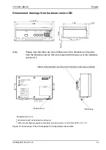
Страница 73: ...s up to the hardware version CC 2 Dimensional drawing applies to standard mounting rail acc to IEC EN 60715 35 7 5 1 Minimum length of standard mounting rail Dimensions in mm Deblocking Crosstip screw Wall mounted standard mounting rail not included in the scope of delivery Error of Link Down Echo Mode Port 1 Data Port 2 Data Power On Reset 1 sec Echo Mode 1 sec Normal Mode Port 3 Port 2 Port 1 Po...

Страница 74: ...English 7XV5461 0Bx00 74 C53000 B1174 C173 5 ...

Страница 75: ...7XV5461 0Bx00 C53000 B1174 C173 5 75 ...

Страница 76: ...r pflichten zu Schadenersatz Alle Rechte für den Fall der Patenterteilung oder GM Eintragung vorbehalten Copying this document and giving it to others and the use or communication of the contents thereof are forbidden without express authority Offenders are liable to the pay ment of damages All Rights are reserved in the event of the grant of a patent or registration of a utility model or design D...

Отзывы: