7XV5461-0Bx00
English
C53000-B1174-C173-5
55
If the devices 7XV5461-0Bx00 are used for the communication over distances shorter than
specified in the technical data (listed in table 1), the transmitting power must be reduced via
optical attenuators (see Figure 11).
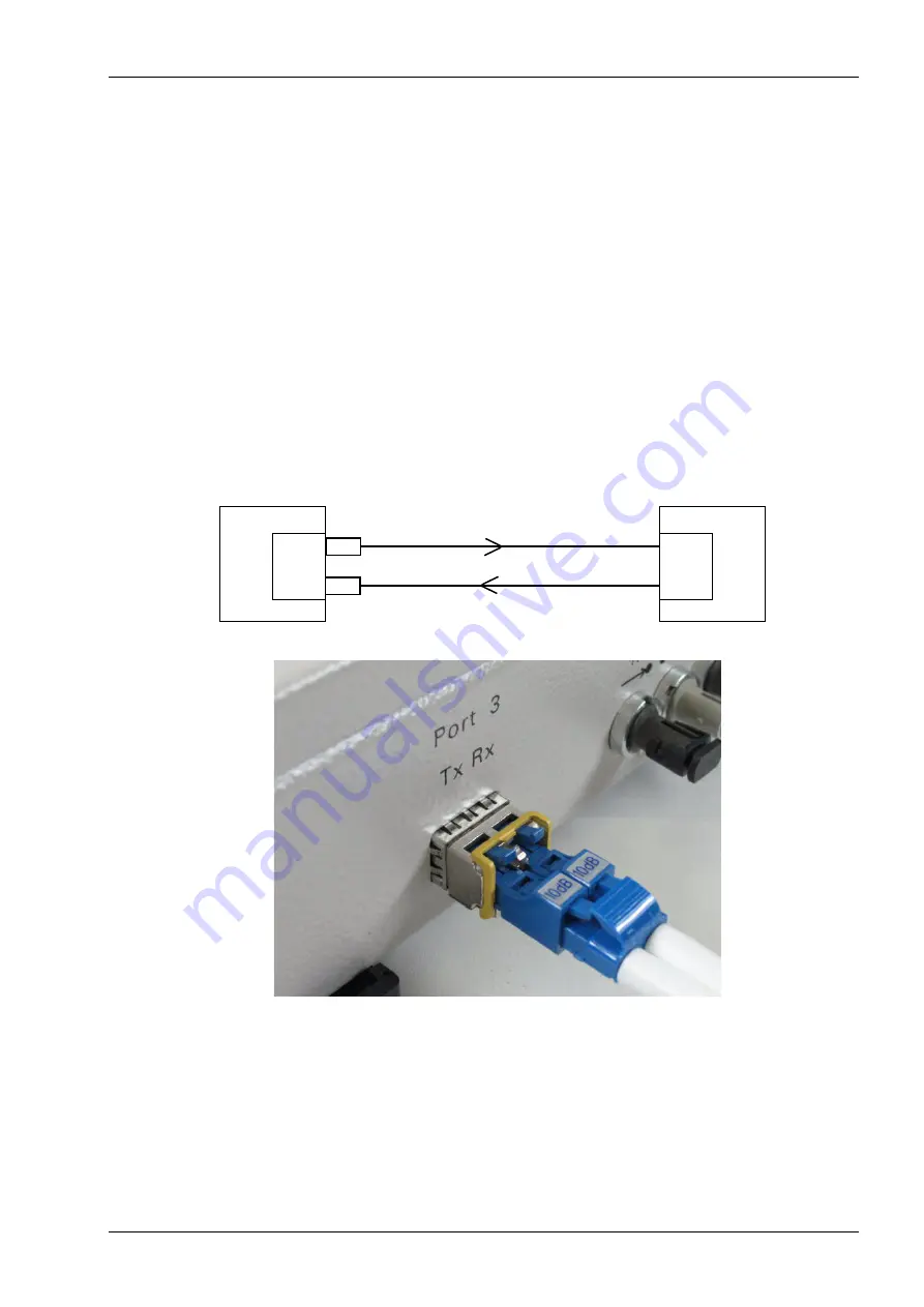
For mounting the attenuators remove their protective caps. Plug one attenuator each, with
the ratchet lever pointing upward, into the Tx and Rx connections of port 3. Make sure the
ratchet levers are properly engaged. Afterwards, connect the LC duplex connector with the
FO cable to the attenuators (see Figure 12, below).
The two attenuators may only be connected to one end of the optical wide area connection
(see Figure 12, above).
Note
:
One attenuator is delivered pro 170 km device variant. When using two of these
device variants for communication, both delivered attenuators must be connected
to the same end of the optical long-distance connection
.
Figure 12 Connecting the LC duplex connector via two attenuators to port 3
Use a screwdriver to fasten the cables of the auxiliary supply voltage to the 2-pin screw-
type terminal
115 - 250VAC / 24 - 250VDC
. The polarity has not been specified.
The DR relay contacts can be connected as a NO contact or a NC contact. If a NC contact
is connected, for example, the contact is interrupted in the event of a FO-Repeater failure.
Remote connection
FO-
Repeater
FO-
Repeater
Device 1
Port 3
7XV5461
7XV5461
Tx
Rx
Port 3
Rx
Tx
10 dB
10 dB
Device 2
Содержание 7XV5461-0B 00 Series
Страница 38: ...Deutsch 7XV5461 0Bx00 38 C53000 B1174 C173 5 ...
Страница 74: ...English 7XV5461 0Bx00 74 C53000 B1174 C173 5 ...
Страница 75: ...7XV5461 0Bx00 C53000 B1174 C173 5 75 ...


