Method of operation
7SV512
V1
36
C53000---G1176---C91
4.3
End fault protection
An end fault is defined here as a short-circuit which
has occurred at the end of a line or protected object,
between the circuit breaker and the current trans-
former set.
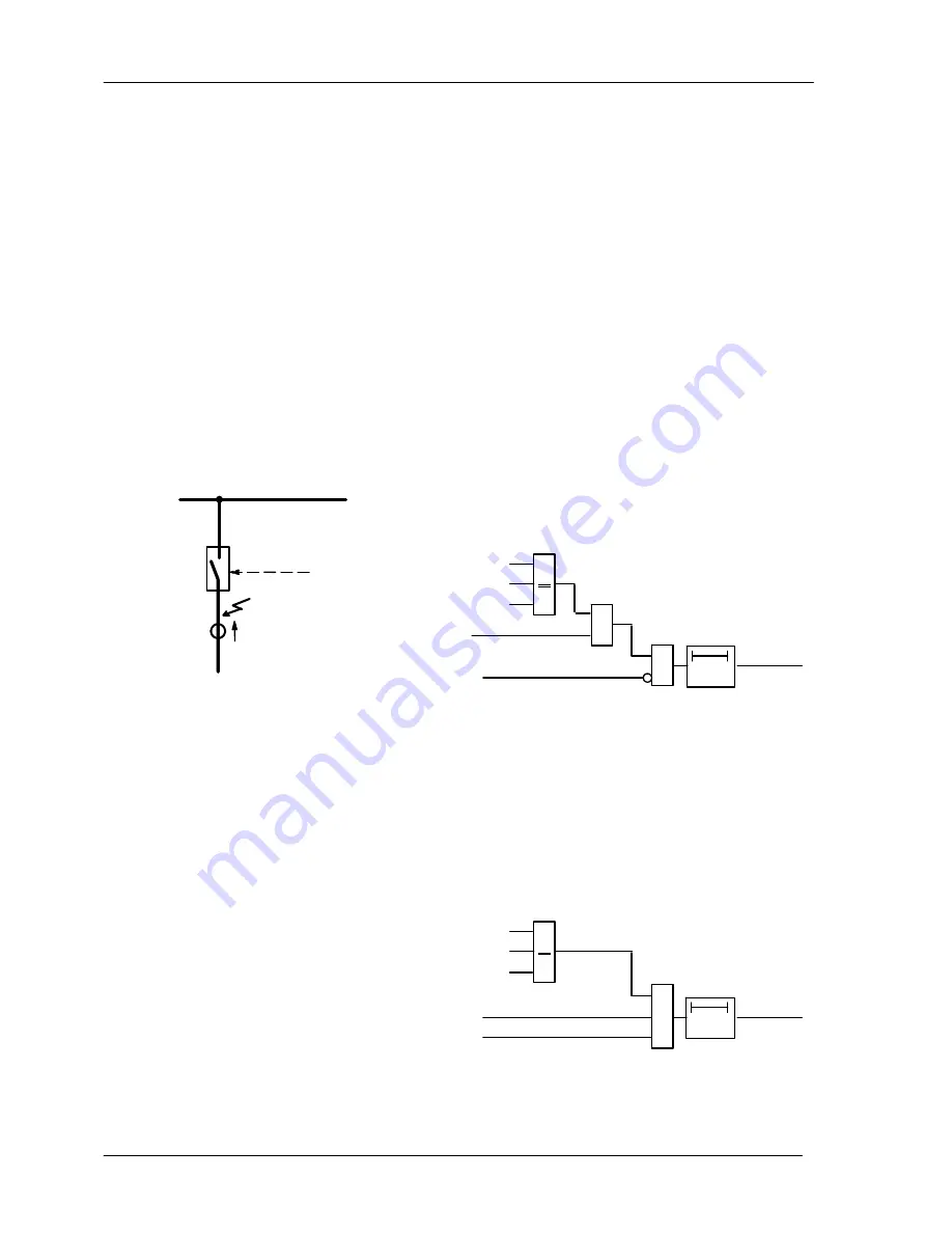
This situation is shown in Figure 4.17. The fault is lo-
cated --- as seen from the current transformers
(= measurement location) --- at the bus-bar side,
thus, it will not be regarded by the feeder protection
relay as a feeder fault. It can only be detected by ei-
ther a reverse stage of the feeder protection or by a
bus-bar protection. Nevertheless, a trip command
given to the feeder circuit breaker cannot clear the
fault since it is continued to be fed from the opposite
end. Thus, the fault current does not stop flowing
even though the feeder circuit breaker has properly
responded to the trip command.
Trip by
protection
Feeder
Bus-
bar
I
sc
Figure 4.17 End fault between circuit breaker
and current transformers
The end fault protection has the task to recognize
this situation and to transmit a trip signal to the re-
mote line end to stop this situation. For this, a trans-
mission channel is required (e.g. power line carrier,
radio wave, or optical fibre).
The end fault is detected by the end fault protection
using the following logic: The end fault is recognized
when the current continues flowing although the cir-
cuit breaker auxiliary contacts indicate that the
breaker is open. In 7SV512, an additional criterion is
the presence of a fault detection signal from the
feeder protection relay. The function scheme is
shown in Figure 4.18. If the feeder protection has
picked up and current flow is recognized (current
criteria ”L*>” according Section 4.2.2, see Figure
4.4), but no circuit breaker pole is closed (auxiliary
contact criterion ”any pole closed” according Sec-
tion 4.2.3, see Figure 4.7), then a timer T---END---FLT
is started, after which an intertrip signal ”
BFP
TransTrip
” is transmitted to the opposite line end.
&
T---END
---FLT
>Start
BFP
TransTrip
>1
&
L2>
L1>
L3>
any pole closed acc. Fig
4.7 (Section 4.2.3)
Figure 4.18 Function scheme of end fault protec-
tion
4.4
Circuit breaker pole discrepancy supervision
This function has the task to detect discrepancies in
the position of the three circuit breaker poles. Under
steady-state conditions, either all three poles of the
breaker must be closed, or all three poles must be
open. Discrepancy is permitted only for a short time
interval during a single-pole auto-reclose cycle.
The function scheme is shown in Figure 4.19. The
signals which are processed here had already been
used for the breaker failure protection. Condition for
pole discrepancy is that at least one pole is closed
(”any pole closed” from Figure 4.7, refer Section
4.2.3), and that not all poles are closed (”any pole
open” from Figure 4.7, refer Section 4.2.3). In addi-
tion, current flow is interrogated (from Figure 4.4, re-
fer to Section 4.2.2).
&
T---DIS---
CREP
Pole-Dis
Trip
>1
L2>
L1>
L3>
any pole closed acc.
Fig 4.7 (Section 4.2.3)
any pole open (Fig 4.7)
Figure 4.19 Function scheme of pole discrepan-
cy supervision
www
. ElectricalPartManuals
. com


