7SR210 & 7SR220 Applications Guide
4.1.2 Auto-Reclose Example 2 (Use of Quicklogic with AR)
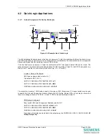
Figure 4.1-2 Example of Logic Application
Requirement: The relay at location ‘A’ it is required to provide a reclose sequence of 2 Instantaneous followed by
2 delayed recloses. Where the fault current level is between the values ‘I1’ and ‘I2’ and the first trip is initiated
from the 51-1 (IDMT) element, the IDMT characteristic should trip the CB and lockout the auto-reclose.
Typical settings are:
CONTROL & LOGIC > AUTORECLOSE PROT’N:
79 P/F Inst Trips: 50-1
79 P/F Delayed Trips: 51-1
CONTROL & LOGIC > AUTORECLOSE CONFIG > P/F SHOTS
79 P/F Prot’n Trip 1 : Inst
79 P/F Prot’n Trip 2 : Inst
79 P/F Prot’n Trip 3 : Delayed
79 P/F Prot’n Trip 4 : Delayed
The above settings are suitable at values of fault current above ‘I2’ however were a fault to occur with a current
value between ‘I1’ and ‘I2’ this would be detected by the 51-1 element only. As
Prot’n Trip 1
=
Inst
then the relay
would trip and reclose whereas it is required to lockout for this occurrence.
To provide a lockout for the above faults an additional element 50-2 with identical settings to 50-1 is assigned as
a Delayed Trip and is used in conjunction with the Quick Logic feature i.e.
OUTPUT CONFIG>OUTPUT MATRIX:
51-1
=
V1
OUTPUT CONFIG>OUTPUT MATRIX:
50-2
=
V2
OUTPUT CONFIG>OUTPUT MATRIX:
E1
=
V3
CONTROL & LOGIC>QUICK LOGIC:
E1
=
V1.!V2
INPUT CONFIG>INPUT MATRIX:
79 Lockout
=
V3
Page 32 of 40
©2011 Siemens Protection Devices Limited


