background image

7SR210 & 7SR220 Applications Guide 

2.7 

Directional Earth-Fault (50/51G, 50/51N, 51/51SEF) 

The directional earth-fault elements, either measure directly or derive from the three line currents the zero 
sequence current (operate quantity) and compare this against the derived zero phase sequence voltage 
(polarising quantity). Section 1 of the Technical Manual ‘Description of Operation’ details the method of 
measurement. The required setting is entered directly as dictated by the system impedances. 

Example: Expected fault angle is -45° (i.e. residual current lagging residual voltage) therefore 

67G Char Angle 

-45°


However directional earth elements can be selectable to use either ZPS or NPS Polarising. This is to allow for the 
situation where ZPS voltage is not available; perhaps because a 3-limb VT is being used. Care must be taken as 
the Characteristic Angle will change if NPS Polarising is used. 

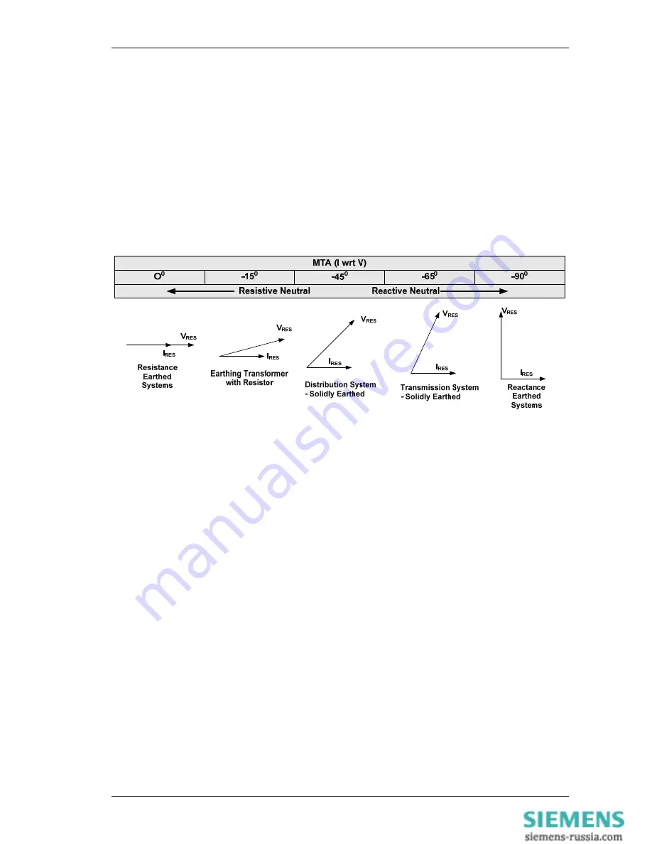
Once again the fault angle is completely predictable, though this is a little more complicated as the method of 
earthing must be considered. 


Figure 2.7-1  Earth Fault Angles 


©2011 Siemens Protection Devices Limited  


Page 21 of 40 

Содержание 7SR210 Argus

Страница 1: ...ed nor shall any model or article be reproduced from this document unless Siemens Protection Devices Limited consent While the information and guidance given in this document is believed to be correct no liability shall be accepted for any loss or damage caused by any error or omission whether such error or omission is the result of negligence or any other cause Any and all such liability is discl...

Страница 2: ...7SR210 7SR220 Applications Guide Document Release History This document is issue 2011 05 2011 05 First issue Page 2 of 40 2011 Siemens Protection Devices Limited ...

Страница 3: ...26 2 13 1 Application with Capacitor Cone Units 27 2 13 2 Derived NVD Voltage 27 2 14 Negative Phase Sequence Overvoltage 47 27 2 15 Under Over Frequency 81 28 Section 3 CT Requirements 29 3 1 CT Requirements for Overcurrent and Earth Fault Protection 29 3 1 1 Overcurrent Protection CTs 29 3 1 2 Earth Fault Protection CTs 29 3 2 CT Requirements for High Impedance Restricted Earth Fault Protection ...

Страница 4: ...tection 19 Figure 2 6 4 Feeder Fault on Interconnected Network 20 Figure 2 7 1 Earth Fault Angles 21 Figure 2 8 1 Balanced and Restricted Earth fault protection of Transformers 22 Figure 2 8 2 Composite Overcurrent and Restricted Earth fault Protection 23 Figure 2 11 1 Thermal Overload Heating and Cooling Characteristic 24 Figure 2 13 1 NVD Application 26 Figure 2 13 2 NVD Protection Connections 2...

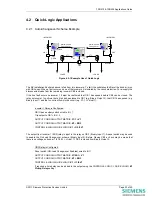
Страница 5: ... see below RADIAL SUBSTATION Start generators Select alternate settings group Local Generation Industrial system draws power from grid system during normal operation Relays normally use settings group 1 On loss of mains Local generation switched in Non essential loads tripped Relays on essential circuits switched to settings group 2 to reflect new load and fault currents Non essential loads Trip n...

Страница 6: ...inary inputs is to provide indication of alarm or fault conditions e g transformer Buchholz Gas or Buchholz Surge conditions The Binary Inputs are mapped to LED s waveform storage trigger and binary outputs Note that transformer outputs which require high speed tripping such as a Buchholz Surge should be wired to a binary input to provide LED indication and also have a parallel connection wired to...

Страница 7: ... to mal operate if they 1 Have both the positive and negative switched double pole switched 2 Do not have extensive external wiring associated with them e g if the wiring is confined to the relay room Where a binary input is both used to influence a control function e g provide a tripping function and it is considered to be susceptible to mal operation the external circuitry can be modified to pro...

Страница 8: ...7 5 V Operative IOP 50 mA 1K2 330 BI DTL 10 ms 10 µF 60 V Capacitance discharge BI DTL 10 ms 10 µF 150 V Capacitance discharge BI 19 V BI 19 V BI 19 V BI 19 V BI 19 V Resistor power ratings 30 V DC Nominal 3 W 48 V DC Nominal 3 W 110 V DC Nominal 10 W ESI 1 110 V DC Nominal 20 W ESI 2 Resistors must be wired with crimped connections as they may run hot 110 V DC Nominal 87 5 V to 137 5 V Operative ...

Страница 9: ...mapped to output functions by means of settings These could be used to display such digital signals as trips a general pick up plant control signals etc User Defined Function Key LEDs are used to indicate the status of Function Key operation These do not relate directly to the operation of the Function Key but rather to its consequences If a Function Key is depressed to close a Circuit Breaker the...

Страница 10: ... or green type the LED number in the appropriate row To assign the required LED as a yellow colour type the LED number in both red and green rows NB If a LED number is not assigned that particular LED will not illuminate Figure 1 4 2 LED configuration via the Settings OUTPUT CONFIG LED CONFIG menu Page 10 of 40 2011 Siemens Protection Devices Limited ...

Страница 11: ...re inversely proportional to the Fault Current being measured This makes them particularly suitable to grading studies where it is important that only the Relay s closest to the fault operate Discrimination can be achieved with minimised operating times To optimise the grading capability of the relay additional time multiplier Follower DTL Fig 2 1 1 or Minimum Operate Time Fig 2 1 2 settings can b...

Страница 12: ...highly arid areas or where the system uses high values of earthing resistor reactance and the fault current detected in the phase conductors will be limited 2 1 1 Selection of Overcurrent Characteristics Each pole has two independent over current characteristics Where required the two curves can be used To produce a composite curve To provide a two stage tripping scheme Where one curve is to be di...

Страница 13: ... for a short time after which the insulation fails again The same phenomenon has occurred in compound filled joint boxes or on clashing overhead line conductors The repeating process of the fault can cause electromechanical disc relays to ratchet up and eventually trip the faulty circuit if the reset time of the relay is longer than the time between successive faults To mimic an electromechanical ...

Страница 14: ...nd this must be above the protection over current settings Close in short circuit faults may also cause the AVR to reach its safety limits for supplying maximum excitation boost in the order of several seconds and this will result in AVR internal protection devices such as diode fuses to start operating The generator excitation will then collapse and the situation will be the same as when no AVR w...

Страница 15: ... be used in blocked overcurrent protection schemes These protection schemes are applied to protect substation busbars or interconnectors etc Blocked overcurrent protection provides improved fault clearance times when compared against normally graded overcurrent relays The blocked overcurrent scheme of busbar protection shown in Figure 2 2 2 illustrates that circuit overcurrent and earth fault prot...

Страница 16: ...olerances and a safety margin a minimum time delay of 100ms is recommended This type of scheme is very cost effective and provides a compromise between back up overcurrent busbar protection and dedicated schemes of busbar protection Instantaneous elements are also commonly applied to autoreclose schemes to grade with downstream circuit reclosers and maximise the probability of a successful auto re...

Страница 17: ... required then it is preferable to use a core balance CT rather than wire into the residual connection of the line CTs The turns ratio of a core balance CT can be much smaller than that of phase conductors as they are not related to the rated current of the protected circuit Since only one core is used the CT magnetising current losses are also reduced by a factor of 3 Circuit 1 Circuit 2 Circuit ...

Страница 18: ...mes termed the Maximum Torque Angle MTA as an analogy to older Electro mechanical type relays Example Expected fault angle is 30º Current lagging Voltage so set Directional Angle to 90 30 60 A fault is determined to be in the selected direction if its phase relationship lies within a quadrant 85 either side of the Characteristic Angle setting Figure 2 6 1 Directional Characteristics A number of st...

Страница 19: ...urrent can flow in both directions at these points The forward direction is defined as being away from the busbar and against the direction of normal load current flow These forward looking IDMTL elements can have sensitive settings applied i e low current and time multiplier settings Note that 7SR22 relays may be programmed with forward reverse and non directional elements simultaneously when req...

Страница 20: ... and reverse directions closed ring circuits can be set to grade correctly whether fault current flows in a clockwise or counter clockwise direction i e it may be practical to use only one relay to provide dual directional protection 2 Out of 3 Logic Sensitive settings can be used with directional overcurrent relays since they are directionalised in a way which opposes the flow of normal load curr...

Страница 21: ...ictated by the system impedances Example Expected fault angle is 45 i e residual current lagging residual voltage therefore 67G Char Angle 45 However directional earth elements can be selectable to use either ZPS or NPS Polarising This is to allow for the situation where ZPS voltage is not available perhaps because a 3 limb VT is being used Care must be taken as the Characteristic Angle will chang...

Страница 22: ... and Restricted Earth fault protection of Transformers The calculation of the value of the Stability Resistor is based on the worst case where one CT fully saturates and the other balancing CT does not saturate at all A separate Siemens Protection Devices Limited Publication is available covering the calculation procedure for REF protection To summarise this The relay Stability operating Vs voltag...

Страница 23: ...urrent of up 3 times phase charging current flowing through the relay location The step change from balanced 3 phase charging currents to this level of zero sequence current includes transients It is recommended to allow for a transient factor of 2 to 3 when determining the limit of charging current Based on the above considerations the minimum setting of a relay in a resistance earthed power syst...

Страница 24: ...or that a low load situation exists For this reason simple Definite Time Lag DTL elements may be used For example once it has been determined that fault current has been broken the CB is open and no current flows an auto isolation sequence may safely be initiated 2 11 Thermal Overload 49 The element uses measured 3 phase current to estimate the real time Thermal State θ of cables or transformers T...

Страница 25: ...y the voltage elements should be set to values safely above below that where a normal system voltage excursion can be expected The switchgear plant design should be considered The Dead level may be very near to the live level or may be significantly below it The variable hysteresis setting allows the relay to be used with all types of switchgear System over voltages can damage component insulation...

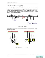
Страница 26: ...earth current would be present to cause a trip but residual voltage would increase significantly reaching up to 3 times the normal phase earth voltage level If Neutral Overvoltage protection is used it must be suitably time graded with other protections in order to prevent unwanted tripping for external system earth faults Figure 2 13 1 NVD Application Typically NVD protection measures the residua...

Страница 27: ... protecting rotating plant such as motors and generators However such protection is almost universally based on detecting NPS Current rather than Voltage This is because the NPS impedance of motors etc is much less than the Positive Phase Sequence PPS impedance and therefore the ratio of NPS to PPS Current is much higher than the equivalent ratio of NPS to PPS Voltage NPS Voltage is instead used f...

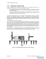
Страница 28: ...hed in stages until the frequency stabilises and returns to an acceptable level The relay has six under over frequency elements An example scheme may have the first load shedding stage set just below the nominal frequency e g between 49 0 49 5Hz A time delay element would be associated with this to allow for transient dips in frequency and to provide a time for the system regulating equipment to r...

Страница 29: ...r there is also the need to consider instantaneous HighSet overcurrent protection as part of the same protection system and the settings would normally be of the order of 10x the CT rating or higher Where higher settings are to be used then the overcurrent factor must be raised accordingly e g to P20 3 1 2 Earth Fault Protection CTs Considerations and requirements for earth fault protection are th...

Страница 30: ... unnecessary lockouts The Sequence Fail Timer provides an overall maximum time limit on the ARC operation It should therefore be longer than all the set delays in a complete cycle of ARC sequences trip delays Deadtimes Reclaim Time etc Generally this will only be exceeded if the circuit breaker has either failed to open or close Since large fault currents could potentially damage the system during...

Страница 31: ...mple 1 Requirement Settings shall provide four phase fault recloses two instantaneous and two delayed and only two recloses for faults detected by the SEF protection Proposed settings include CONTROL LOGIC AUTORECLOSE PROT N 79 P F Inst Trips 50 1 79 P F Delayed Trips 51 1 79 SEF Delayed Trips 51SEF 1 CONTROL LOGIC AUTORECLOSE CONFIG 79 Num Shots 4 CONTROL LOGIC AUTORECLOSE CONFIG P F SHOTS 79 P F...

Страница 32: ...ip 1 Inst 79 P F Prot n Trip 2 Inst 79 P F Prot n Trip 3 Delayed 79 P F Prot n Trip 4 Delayed The above settings are suitable at values of fault current above I2 however were a fault to occur with a current value between I1 and I2 this would be detected by the 51 1 element only As Prot n Trip 1 Inst then the relay would trip and reclose whereas it is required to lockout for this occurrence To prov...

Страница 33: ...utput 2 that CB 1 has opened e g Binary Input 1 and that no current flows in the circuit e g 37 1 Virtual 1 Incomer 1 Relay is Configured CB1 Open auxiliary switch wired to B I 1 Trip output to CB1 B O 2 OUTPUT CONFIG OUTPUT MATRIX 37 1 V1 OUTPUT CONFIG OUTPUT MATRIX E1 BO3 CONTROL LOGIC QUICK LOGIC E1 O2 I1 V1 The output from Incomer 1 BO3 relay is input to the relay on CB 3 Binary Input 1 A pane...

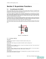
Страница 34: ...used to re trip the local CB to minimise potential disruption to the system if possible via a secondary trip coil and wiring The second CB Failure stage will then be used to back trip the adjacent CB s If the CB is faulty and unable to open a faulty contact can be wired to the CB faulty input of the relay and if a trip occurs while this input is raised the CB fail delay timers may be by passed to ...

Страница 35: ...is as below CB Backtrip Sucessful 20 40 60 80 100 120 140 160 180 200 220 240 260 280 300 320 340 System Fault ms from fault occuring Relay Operation and CBF Timer Started Main Trip Relay Operation Failure of CB to trip Reset of CBF elements does not occur Backtrip Operation Backtrip Trip Relay CB Operate Time Stage 1 CBF Timer Backtrip 120ms Figure 5 1 2 Single Stage Circuit Breaker Fail Timing S...

Страница 36: ...es NPS voltage to restrain the CTS algorithm as show in the accompanying table NPS Current NPS Voltage Decision Setting Setting System Fault Setting Setting CT Failure Table 5 2 Determination of CT Failure 1 or 2 Phases Following a CT Failure there should be little or no NPS voltage Perhaps 0 1 x Vn as a maximum Operation is subject to a time delay to prevent operation for transitory effects A 3 p...

Страница 37: ...e possible problems with using NPS quantities due to load imbalances These would also generate significant levels of NPS current and so possibly cause a VT failure to be missed This problem can be overcome by careful selection of settings however setting the NPS current threshold above the level expected for imbalance conditions If a failure occurs in all 3 Phases of a Voltage Transformer then the...

Страница 38: ...ssages while the circuit breaker is operating the input is given a 0 4s Drop off Delay in the INPUT CONFIG BINARY INPUT CONFIG menu To provide an alarm output a normally open binary output is mapped to 74TCS n 5 4 1 Trip Circuit Supervision Connections The following circuits are derived from UK ENA S15 standard schemes H5 H6 and H7 For compliance with this standard Where more than one device is us...

Страница 39: ... Closed It does not provide pre closing supervision of the connections and links between the tripping contacts and the circuit breaker and may not therefore be suitable for some circuits which include an isolating link Scheme 3 Comprehensive BI ve ve BO BI ve ve TRIP COIL 52a 52b Circuit Breaker TRIP CCT n FAIL BO 1 BO n Remote Alarm 7SR24 R R H7 Scheme Notes BI 19V 48 110 220V supply R 3K3 typica...

Страница 40: ...monic content derived for all 3 phases and then compared to Fundamental current for each individual phase Provides good compromise between Inrush stability and fast fault detection Table 5 5 Magnetic Inrush Bias 5 6 Broken Conductor Load Imbalance 46BC This feature is used to detect an open circuit condition when a conductor breaks or a mal operation occurs in phase segregated switchgear There wil...

Отзывы: