


SIEMENS Energy & Automation
10-53
SIMOREG DC Master Base Drive Panel Operating Instructions
PNU
Description
Value range
[Unit]
Steps
No. indices
Factory
setting
Type
See
Change
(Access /
Status)
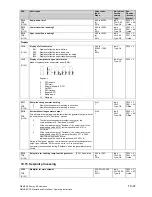
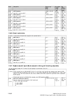
10.27 Configuring of torque shell input
P500
*
BDS
(G160)
Source for torque setpoint for slave drive
Selection of the connector to be injected as the
torque setpoint for a slave
drive
0 = connector K0000
1 = connector K0001
etc.
All connector
numbers
1
Ind: 2
FS=170
Type: L2
P052 = 3
P051 = 40
Offline
P501
*
BDS
(G160)
Source for additional torque setpoint
Selection of connector to be injected as the
additional torque setpoint
0 = connector K0000
1 = connector K0001
etc.
All connector
numbers
1
Ind: 2
FS=0
Type: L2
P052 = 3
P051 = 40
Offline
P502
*
(G152)
Source for value to be added to speed controller output
Selection of connector to be injected as the value to be added to the speed
controller output (in addition to friction and moment of inertia compensation)
0 = connector K0000
1 = connector K0001
etc.
All connector
numbers
1
Ind: None
FS=0
Type: L2
P052 = 3
P051 = 40
Offline
P503
FDS
(G160)
Multiplier for torque setpoint in slave mode
-300.00 to 300.00
[%]
0.01%
Ind: 4
FS=100.00
Type: I2
P052 = 3
P051 = 40
on-line
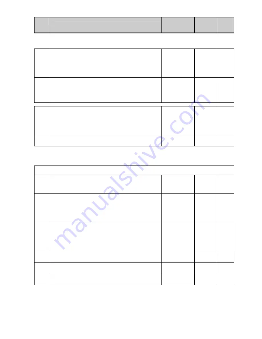
10.28 Speed limiting controller
(see also Section 8, Sheet G160
of Operating Instructions 6RX1700-0AD**
)
The output of the speed limiting controller comprises a positive (K0136) and a negative (K0137) torque limit. These limits are applied to
the torque limitation
P509
*
(G160)
Source for input quantity (n-act) of speed limiting controller
0 = connector K0000
1 = connector K0001
etc.
All connector
numbers
1
Ind: None
FS=167
Type: L2
P052 = 3
P051 = 40
Offline
P510
*
(G160)
Source for pos. torque limit of speed limiting controller
Selection of the connector to be injected as the
limit value for torque
limitation 1
0 = connector K0000
1 = connector K0001
etc.
All connector
numbers
1
Ind: None
FS=2
Type: L2
P052 = 3
P051 = 40
Offline
P511
*
(G160)
Source for neg. torque limit of speed limiting controller
Selection of the connector to be injected as the
limit value for torque
limitation 2
0 = connector K0000
1 = connector K0001
etc.
All connector
numbers
1
Ind: None
FS=4
Type: L2
P052 = 3
P051 = 40
Offline
P512
FDS
(G160)
Maximum speed in positive direction of rotation
0.0 to 199.9
[%]
0.1% of rated speed
Ind: 4
FS=105.0
Type: O2
P052 = 3
P051 = 40
Online
P513
FDS
(G160)
Maximum speed in negative direction of rotation
-199.9 to 0.0
[%]
0.1% of rated speed
Ind: 4
FS=-105.0
Type: I2
P052 = 3
P051 = 40
Online
P515
FDS
(G160)
P gain of speed limiting controller
0.10 to 200.00
0.01
Ind: 4
FS=3.00
Type: O2
P052 = 3
P051 = 40
Online
Содержание 6RA70 Series
Страница 9: ...1 4 Siemens Energy Automation SIMOREG DC Master Base Drive Panel Operating Instructions NOTES ...
Страница 23: ...3 12 Siemens Energy Automation SIMOREG DC Master Base Drive Panel Operating Instructions NOTES ...
Страница 25: ...4 2 Siemens Energy Automation SIMOREG DC Master Base Drive Panel Operating Instructions NOTES ...
Страница 31: ...5 6 Siemens Energy Automation SIMOREG DC Master Base Drive Panel Operating Instructions NOTES ...
Страница 45: ...6 14 Siemens Energy Automation SIMOREG DC Master Base Drive Panel Operating Instructions NOTES ...
Страница 60: ...Siemens Energy Automation 7 15 SIMOREG DC Master Base Drive Panel Operating Instructions NOTES ...
Страница 69: ...7 24 Siemens Energy Automation SIMOREG DC Master Base Drive Panel Operating Instructions NOTES ...
Страница 89: ...8 20 Siemens Energy Automation SIMOREG DC Master Base Drive Panel Operating Instructions NOTES ...
Страница 121: ...9 32 Siemens Energy Automation SIMOREG DC Master Base Drive Panel Operating Instructions NOTES ...
Страница 125: ...10 4 SIEMENS Energy Automation SIMOREG DC Master Base Drive Panel Operating Instructions NOTES ...
Страница 215: ...10 94 SIEMENS Energy Automation SIMOREG DC Master Base Drive Panel Operating Instructions NOTES ...